
Foremost, this power distributor solution is not a final one. We need a distributor that can divide about twenty amperes into 2×5A, 3×1.5A and 1×1A plus the current needed by the microcontroller.
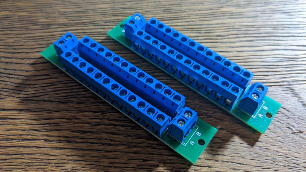
The chosen power distributor is from a model railway and can only distribute 10A current. We have to use twice for an adequate usage.
I purchased two in a set from Amazon. Here is a Link to the product. They cost 5 EUR each.
UPDATE: I changed the design from the power supply unit (PSU). Now there is only on power distributor for the four TB6600 needed. The DM556 Drivers w’ll have a direct connection to the PSU. For more information, check out part 14.
3D Prints

I modelled a DIN rail bracket for the power distributors. This is basically the same bracket from the last part but with another screw hole arrangement.
Preparation

BOM
Step 1: Install the power distributors
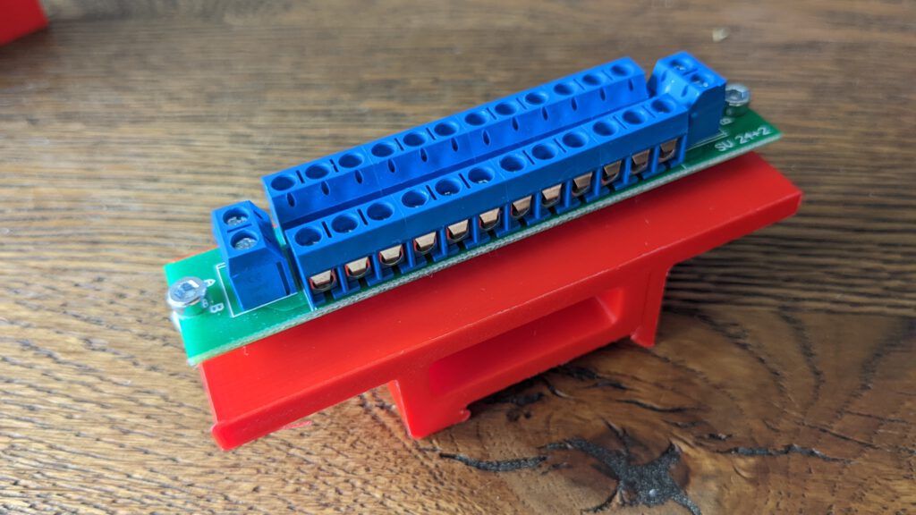
You only have to screw the PCB’s on top of the DIN RAIL brackets.
Step 2: Power wiring
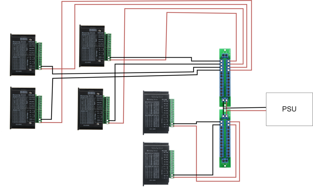
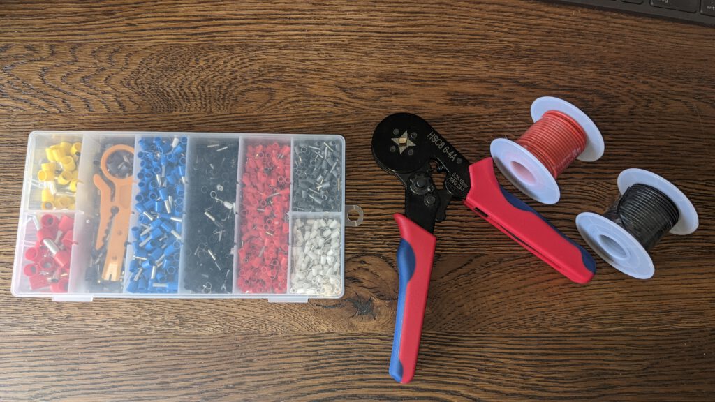
Every power cable from the distributor to the motor drivers is an 18AWG 0.81 mm2 cable. The 18AWG cable is rated for currents up to 8.0A. I’m using this cable, but you can use a 20AWG 0.5 mm2, too (rated for currents up to 5.0A). In my case, I want to be sure that the cable is not the bottleneck.

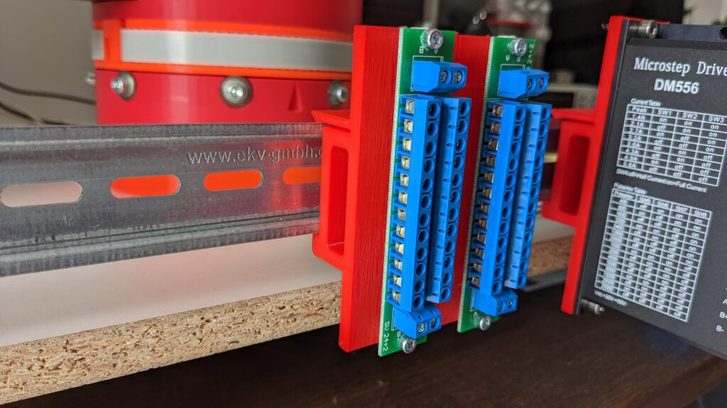
I would like to arrange the drivers and the distributors (PD) between the microcontroller (µC) and the poser supply unit (PSU). The PSU will be placed right next to the distributors and the microcontroller will be next to the drivers. With this arrangement, we can optimize our cable management.
In this part, we’ll only cover the wiring from PD’s to the drivers.
Step 3: Cable Preparation
I’m cutting the power cables for GND and VCC to the following lengths
- 24 cm
- 20 cm
- 16 cm
- 14 cm

Step 4: Mounting
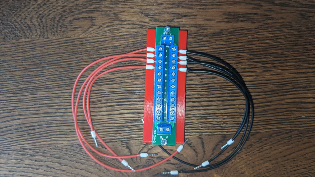
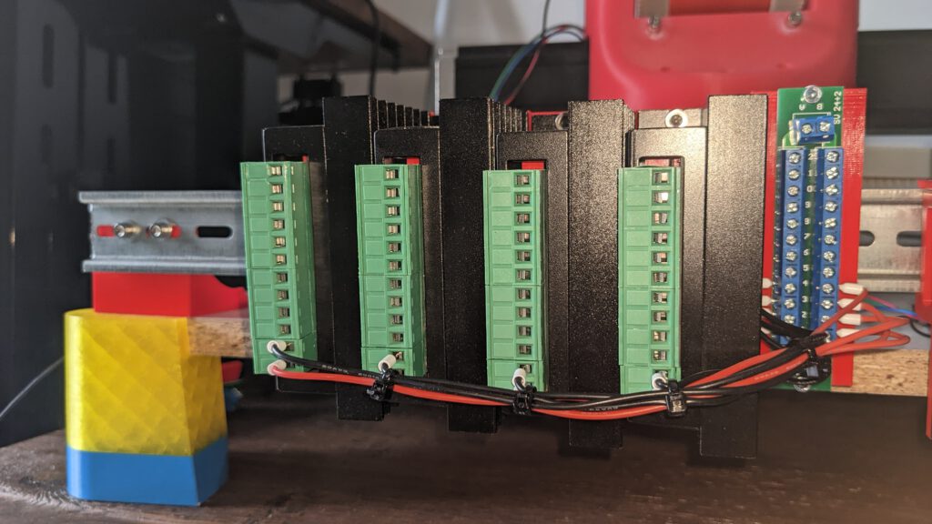
After the installation from the cables into the power describers, I connected the screw terminals.
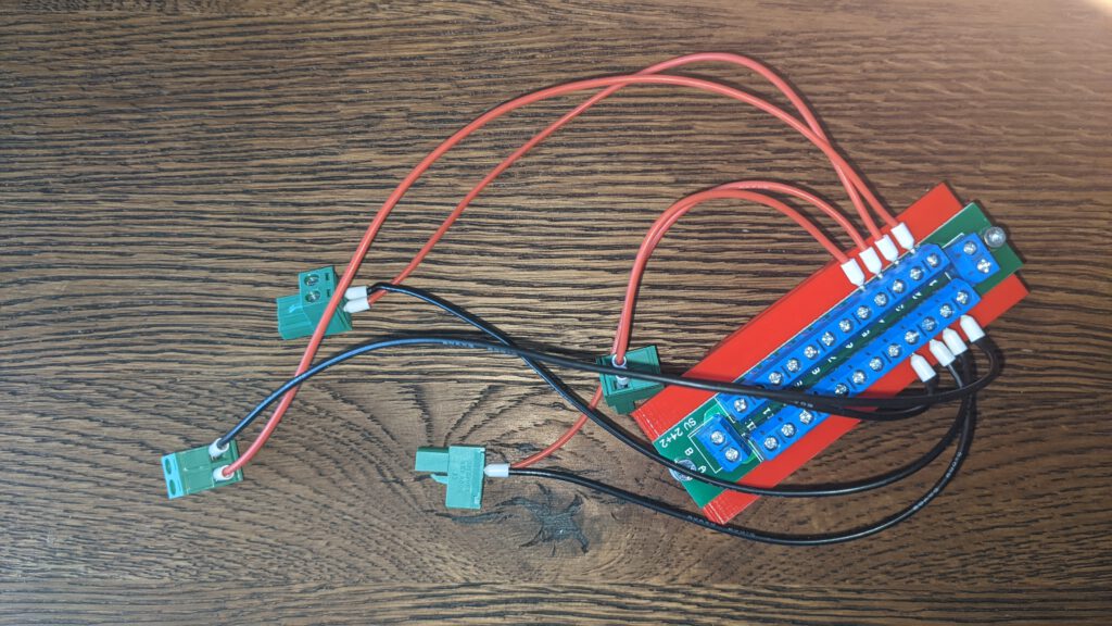
After this, I installed the PD onto the DIN Rail and inserted the plugs into the motor drivers.
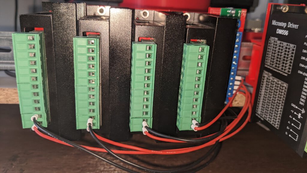
Thanks to four zip ties, I could establish some order into the cable arrangement.
Leave a Reply