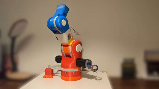
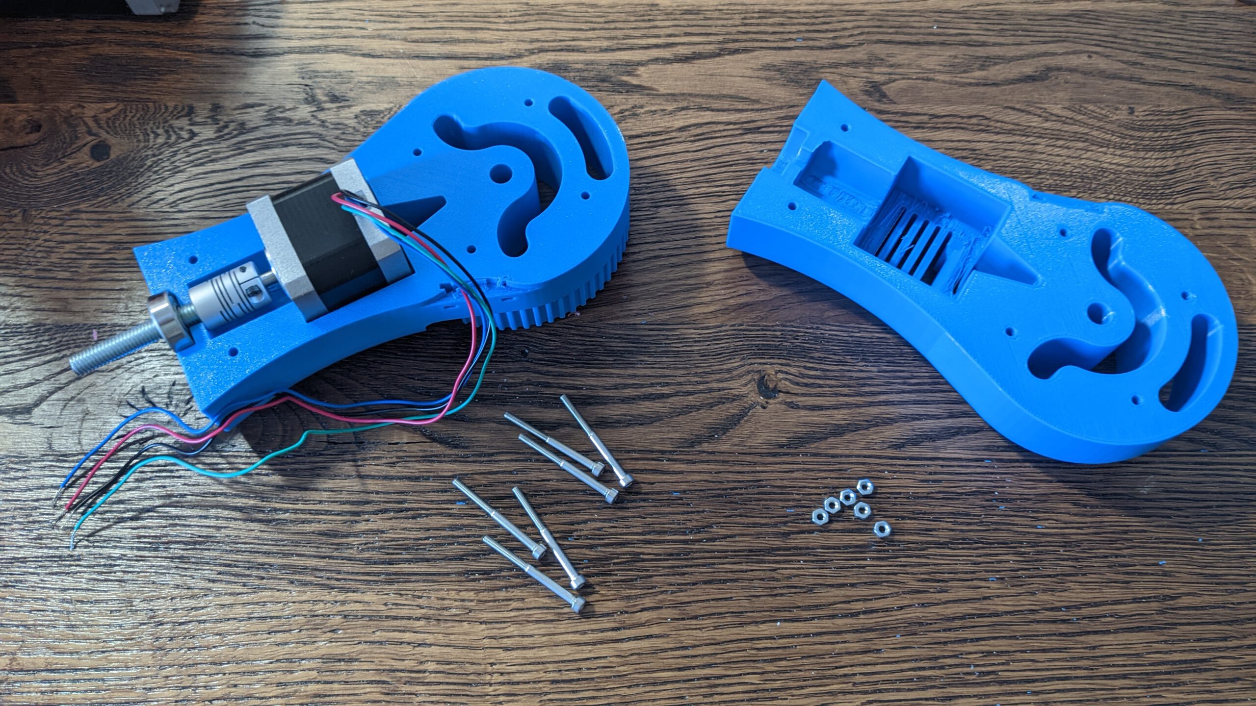
The 3rd module does not come with bigger issues. It was quite convenient to set everything up. In the last part, I made a mistake where I glued the M3 brass inserts into the hole. Now I knew that there are heat inserts. And with some head, it is straightforward to install them. Although I have to glue the M4 inserts in place because the inserts are too small for the hole.


Preparation
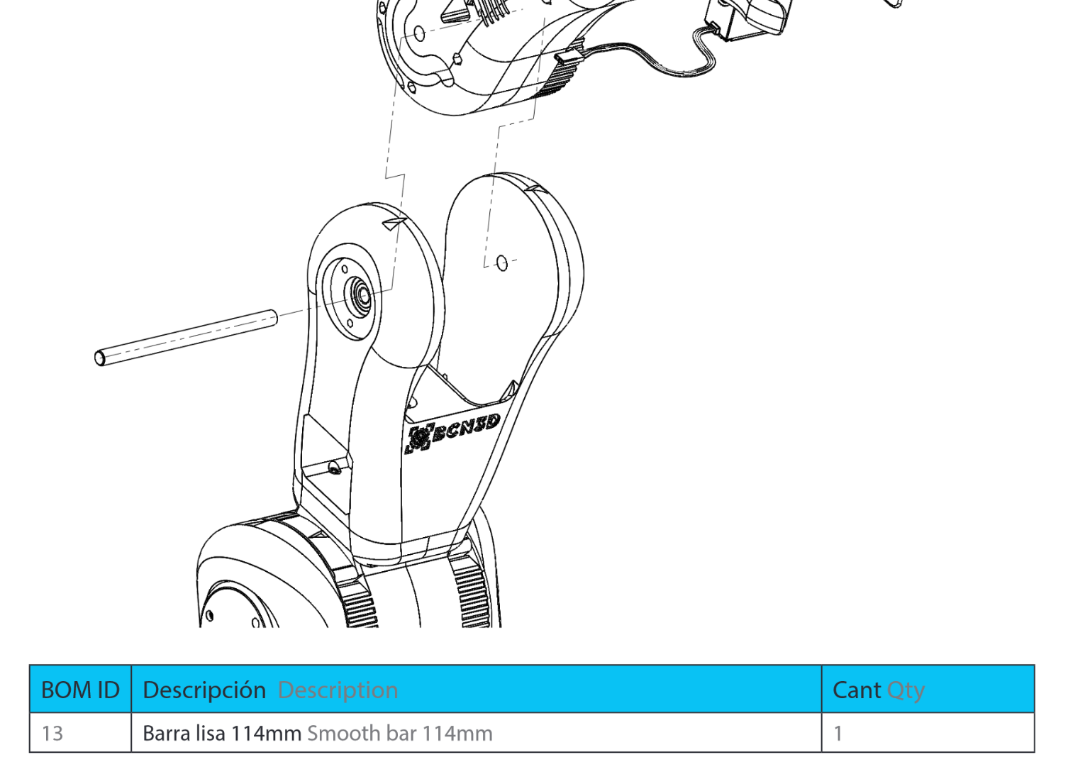
BOM for part 3
Tools
- HX4 Screw driver
- HX2 Screw driver (for the pulley)
- Solder Iron
Step 1: Mount 2M1
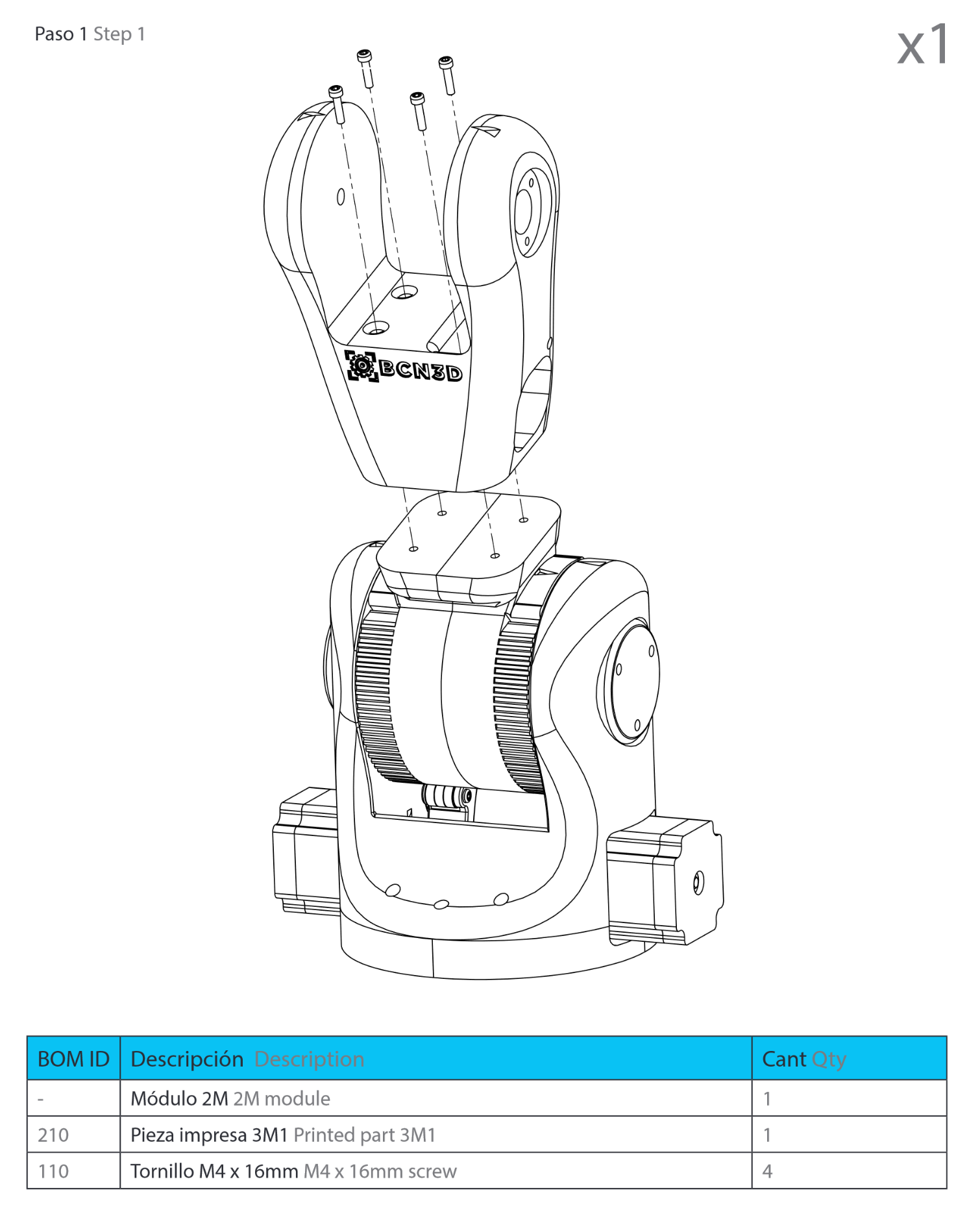
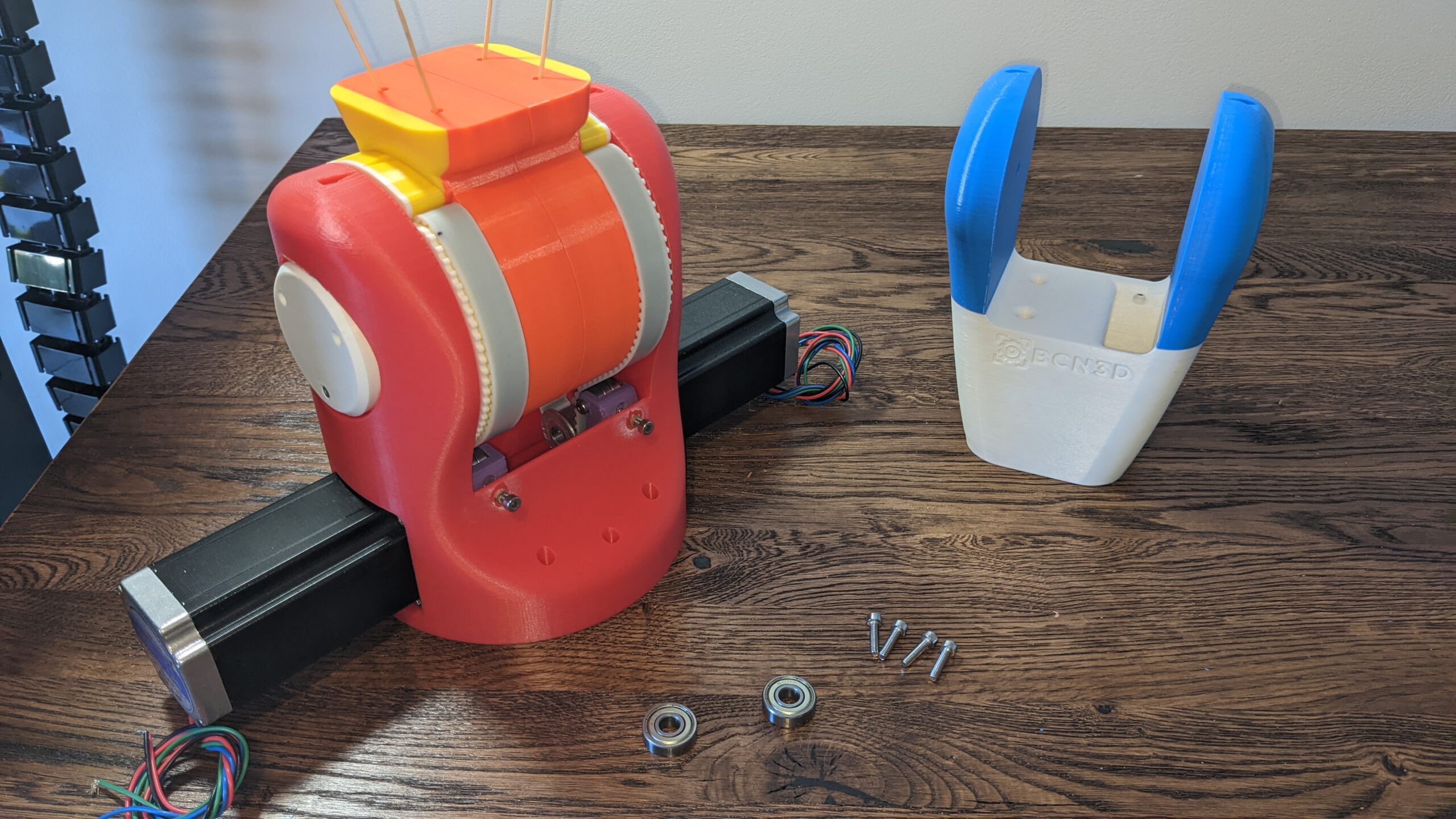
The screws in the 1M1part a lose. I had to hold them with some tooth sticks into place. Then I mounted the 2M1 part on top of this.
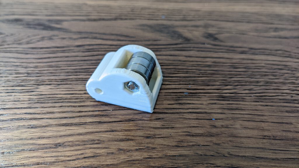
Step 2: prepare the belt stretcher
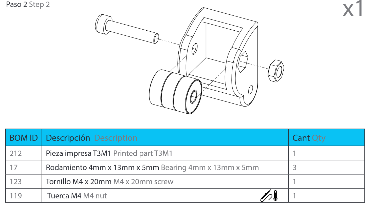
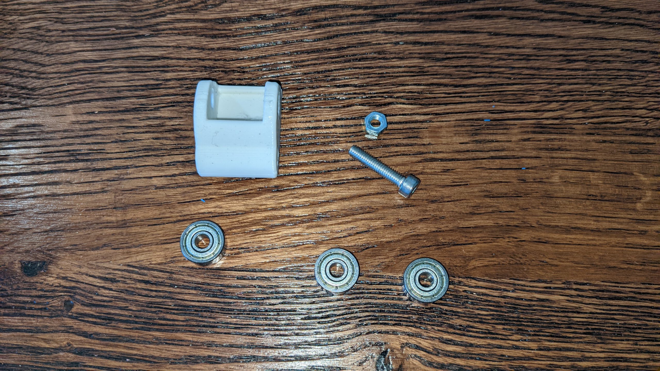
This time, my printer could handle the hexagon hole. I did not have to modify the printed piece.
Step 3: Mounting the belt stretcher
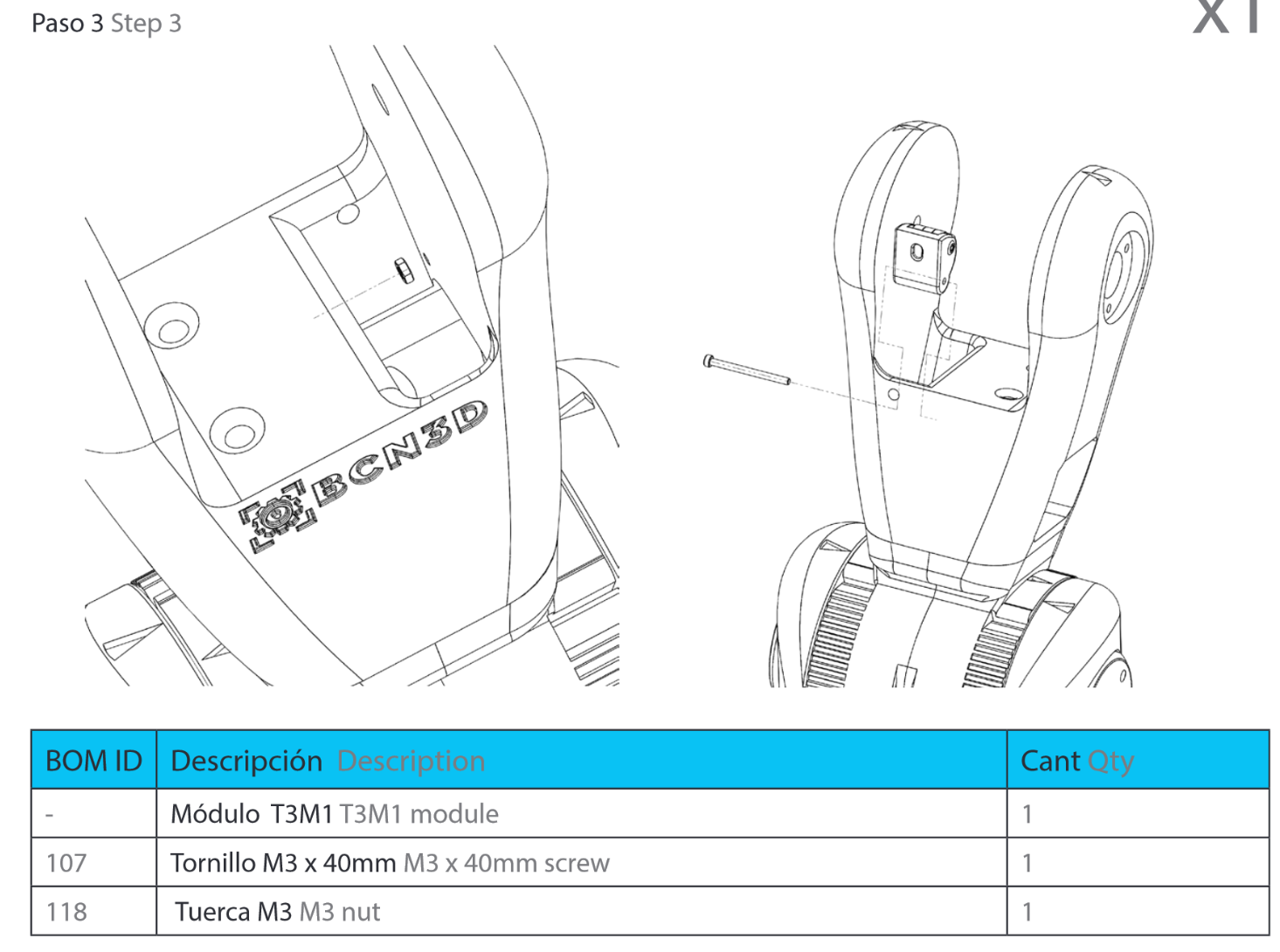
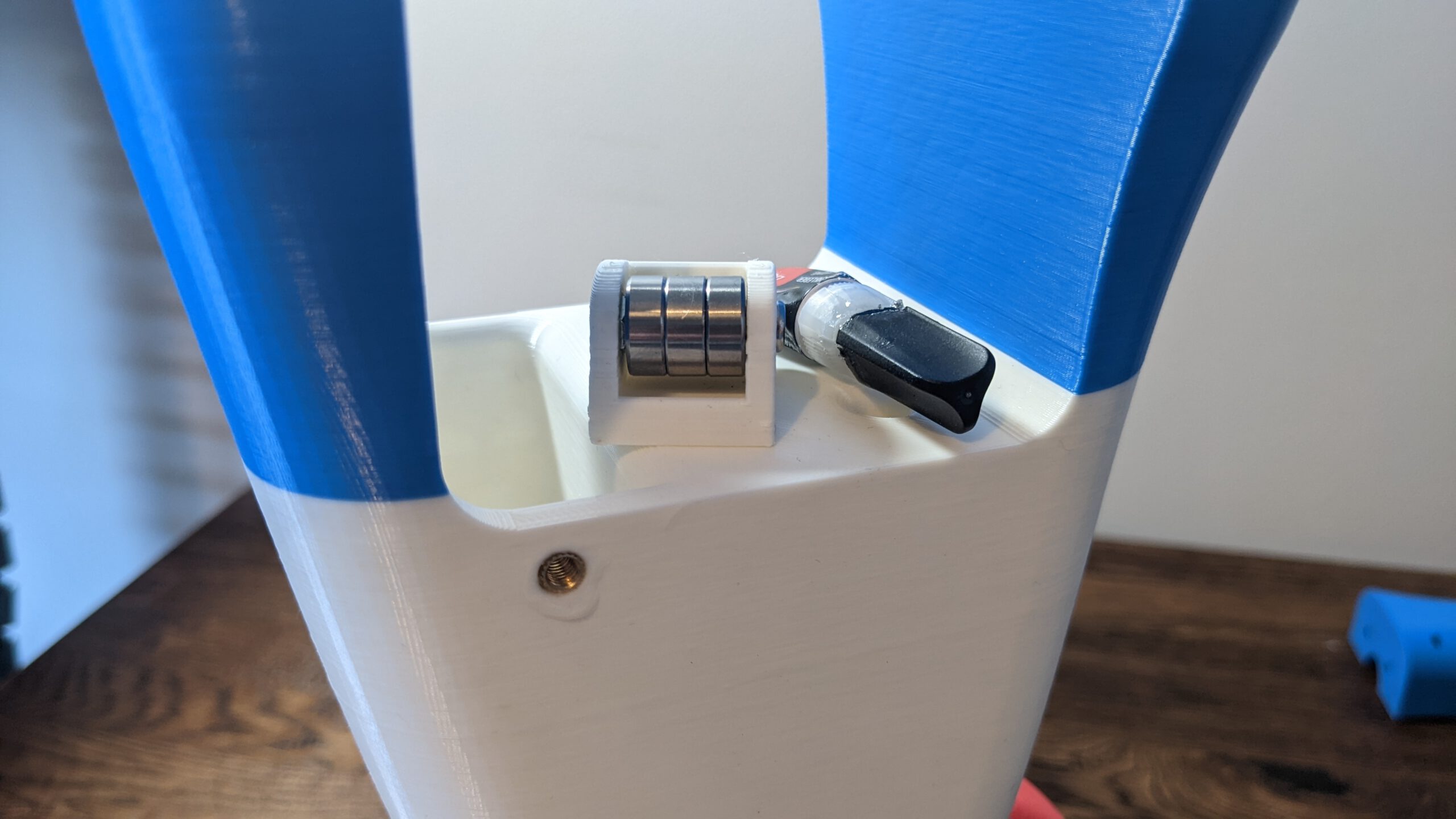
The M4 screw inserts didn’t fit here, either. I had to glow them in again.
In the future, I have to find the correct inserts but for now, this is the way I’ll do it
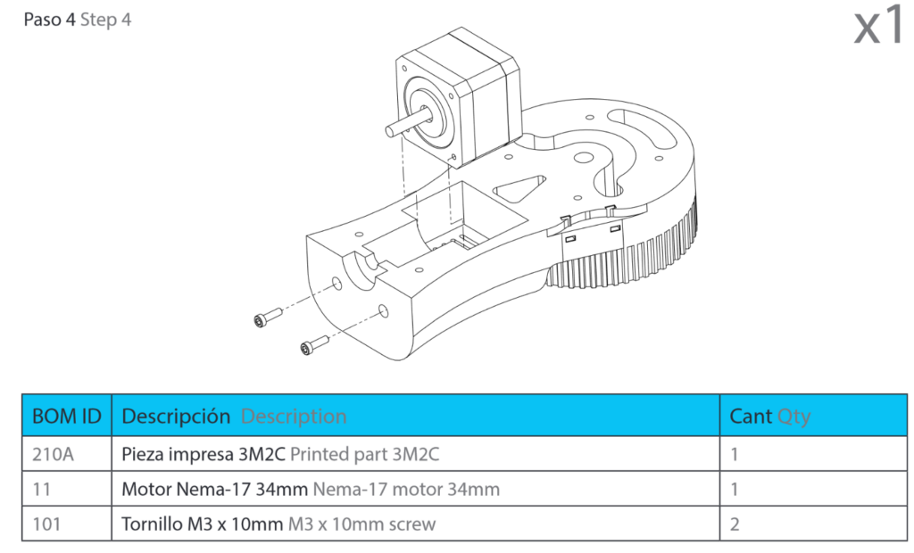
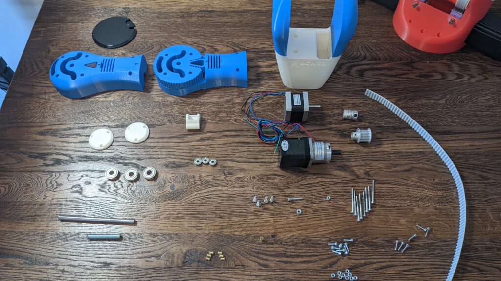
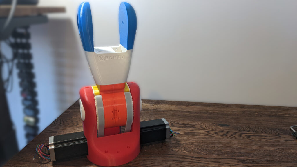
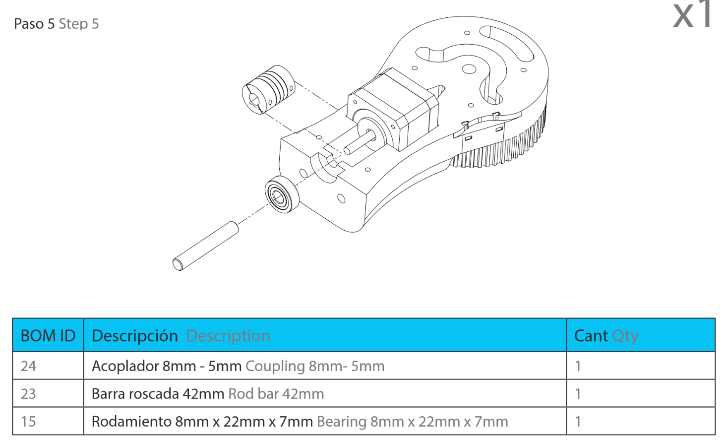
Step 4: 3M2 Assembly
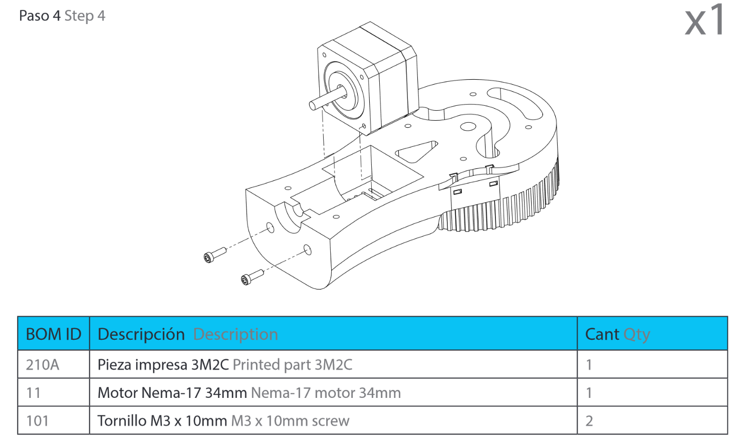


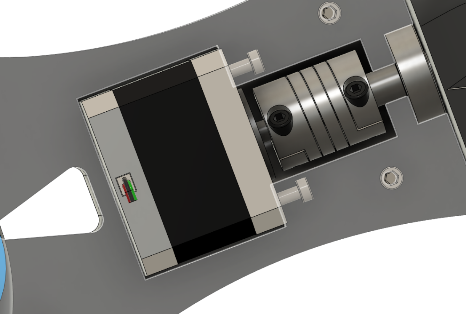
We have edited the 3M2 parts (3M2C & 3M2CC) to fit our stepper motor inside. For the detailed changes, have a look at hit blog post:
Unfortunately I have not time to finish this week’s blog post in time. I take this week off and I will describe the second half of the post in next weeks blog entry.
Leave a Reply