The manual has no intuitive way to build the arm. In the first steps you should build the 1M2 Base and everything needed for the Base but instead to build the Base complete you should build the hole arm and then complete the base. In my opinion, this isn’t an ideal solution.
In this part, we will be doing the following steps. Please see the manual if you have any questions.


Building
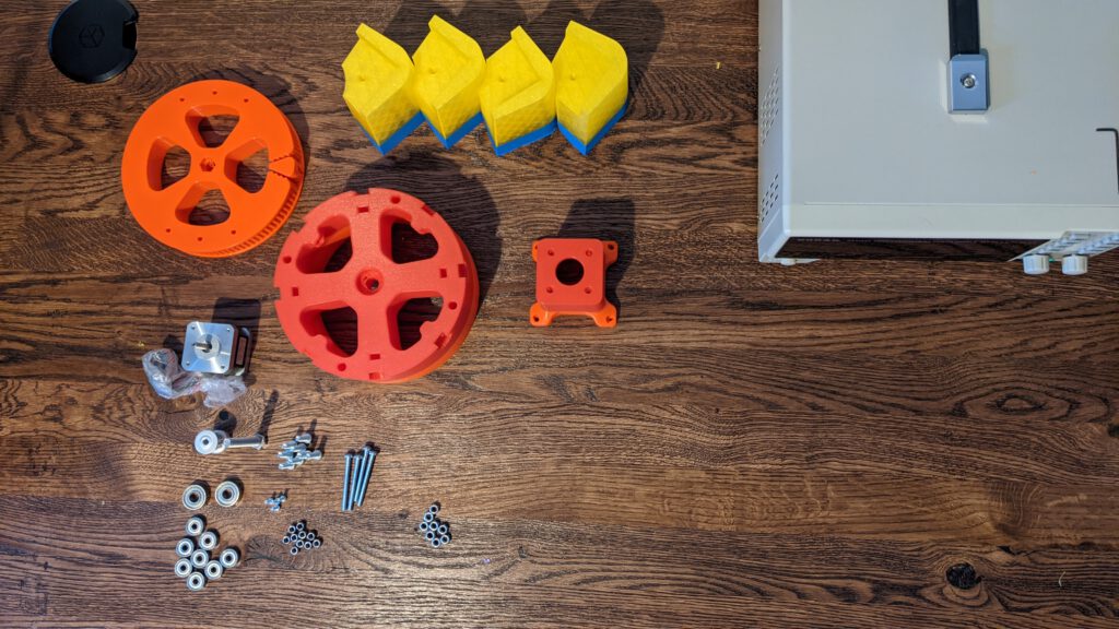
In this first section, we will show the required items. Then we will build this parts step by step. If I make an error or miss something in the BOM, I’ll update the BOM so you don’t have to troubleshoot like me.
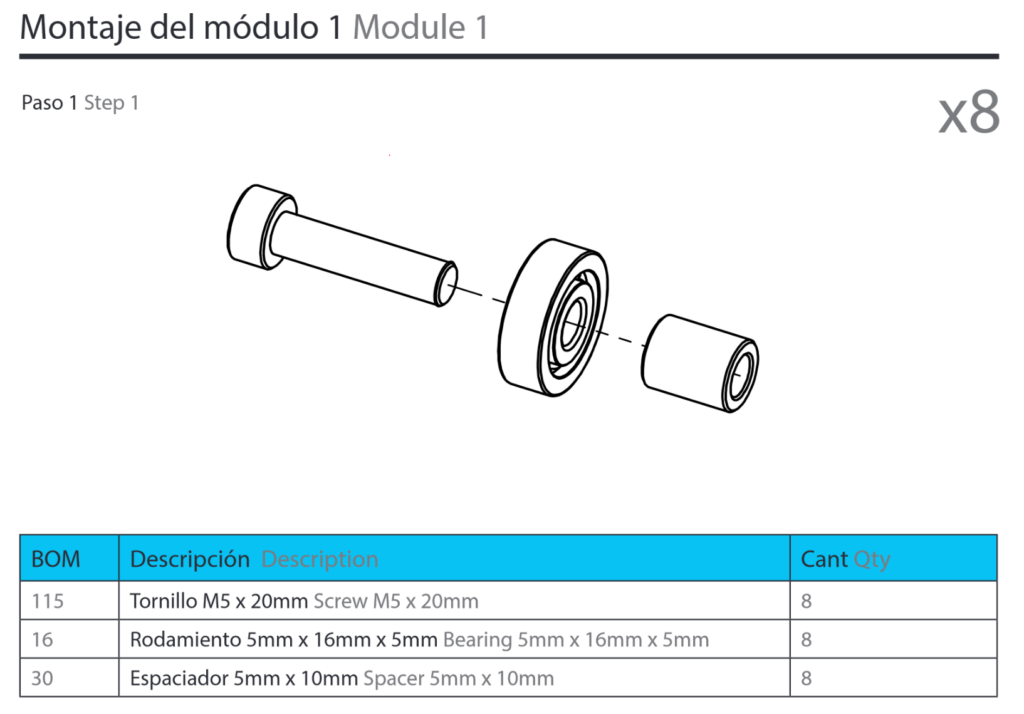
BOM Part 1
Tools
- 8 mm drill
- 5.3 mm drill
- 4.3 mm drill
- 35 – 80 mm hole saw
- HX4 Screw driver
- Carpenter angle
- Marker
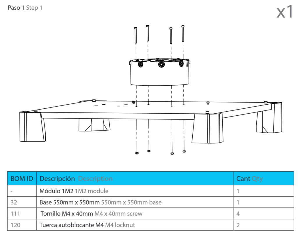
Step 1
Building the base. First, I could not find a schematic where the holes should be in the wood plate. So, I have to create my own. Please note that I didn’t drill the holes for the electronics. The big hole in the centre has no technical use. It only provides use with the ability to tighten the M8 nut for the arm. The diameter for this hole can be anything between 35 mm and 80 mm. I drilled with a 60 mm hole saw my hole.
EDIT: The holes for the posts should have a diameter of 5.3 mm because we will use M5x30 Screws to fix them.
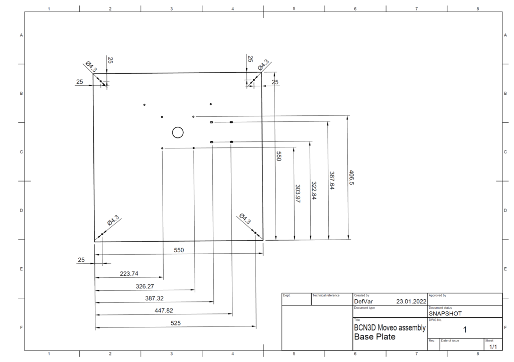
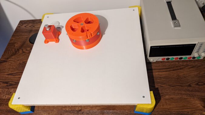
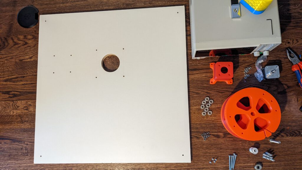
This is the baseplate with holes.
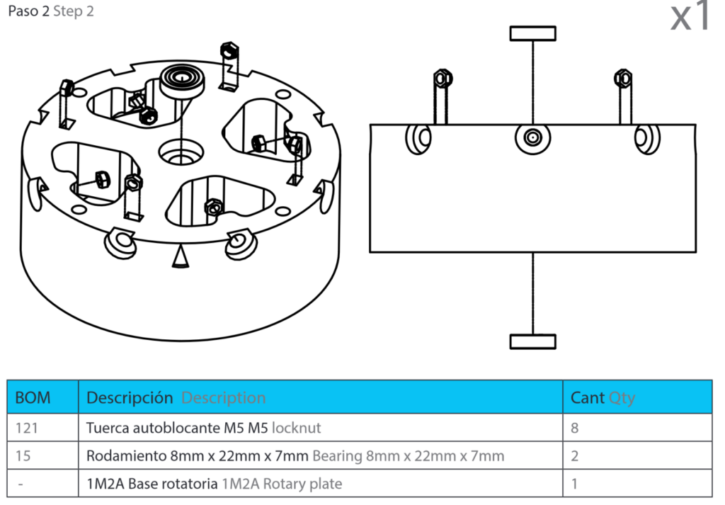
Step 2
In the user manual, I could not find the step where the base posts are installed. This is not a difficult step.
EDIT: You should use the Screws M5x30 (BOM ID 128) to install the posts. I had troubles with the M4 x 30 Screws and with the M4 nuts.
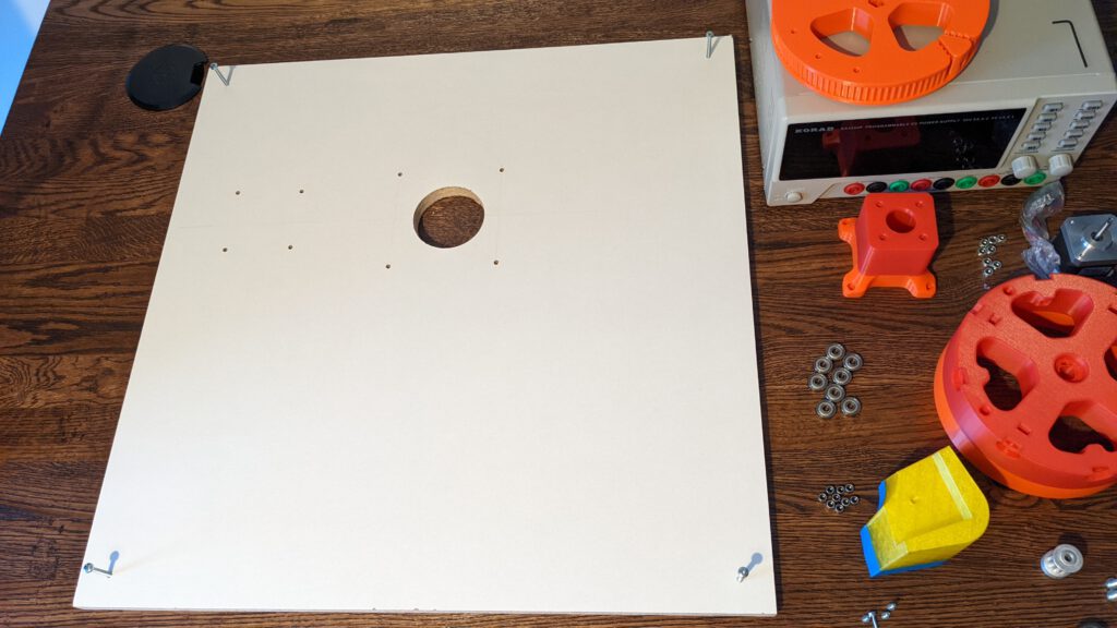
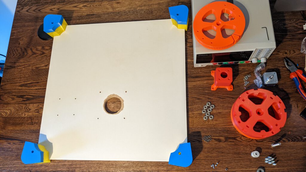

I had some troupe tightening up the posts to the base because my nuts have a thinner diameter. To tightening the nut, I stick some toothpicks between the nut and the border.

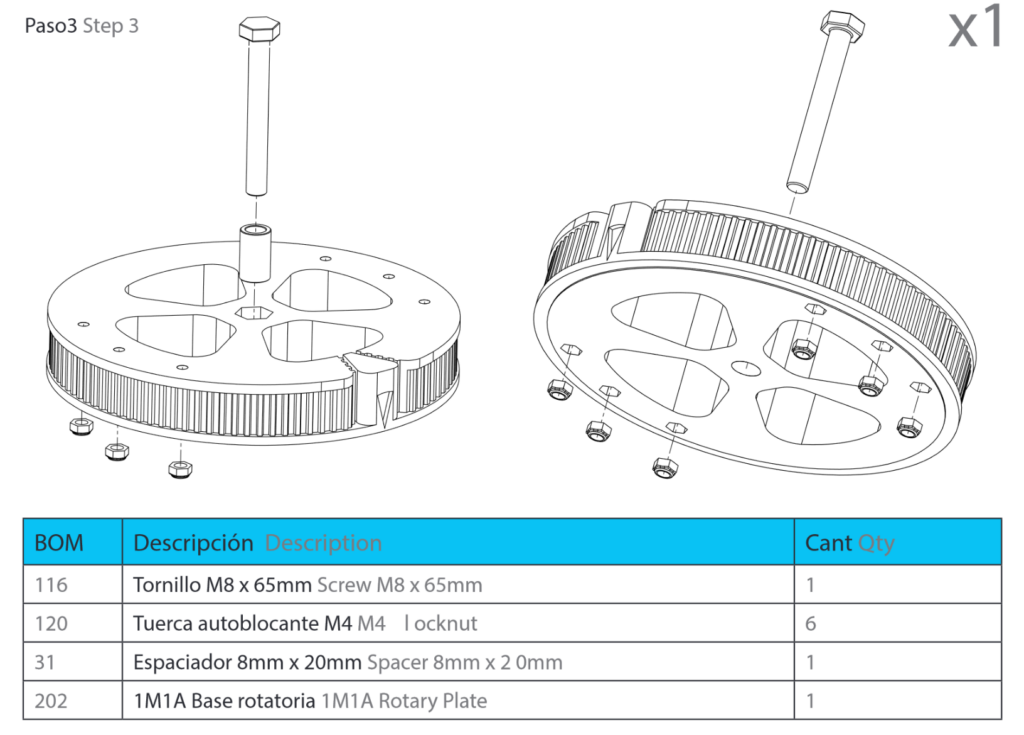
Step 3

With my sleeves, I had some issues because the inner diameter is smaller than 5 mm. In the CAD-Model I choose the inner diameter to be exact 5 mm but with the tolerance form, the slicer and printer it comes out to be 4.8 mm. I have to change the 3D model at some point, but for now, I drilled the holes up with a 5 mm drill.
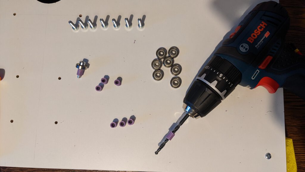
After the drilling, it was effortlessly to create the 8 pieces.

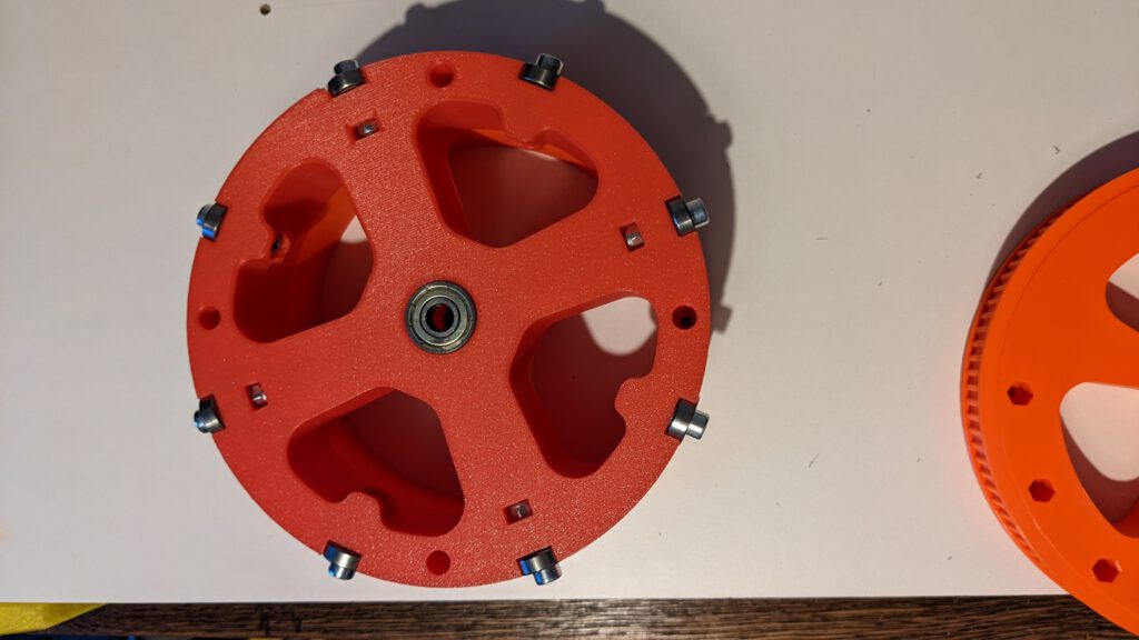
Step 4
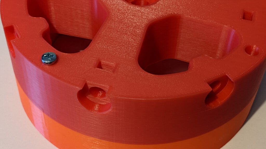
In this step, we will insert the locknuts into the 1M2 part. After that, we can screw in the items from step 3. Now we can insert the bearings in the top and the bottom as shown in the manual. There were no issues for me in this step to address. The final result should look like the following picture.
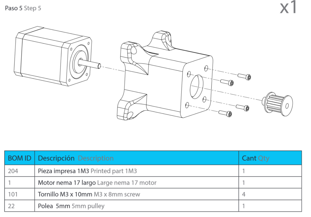
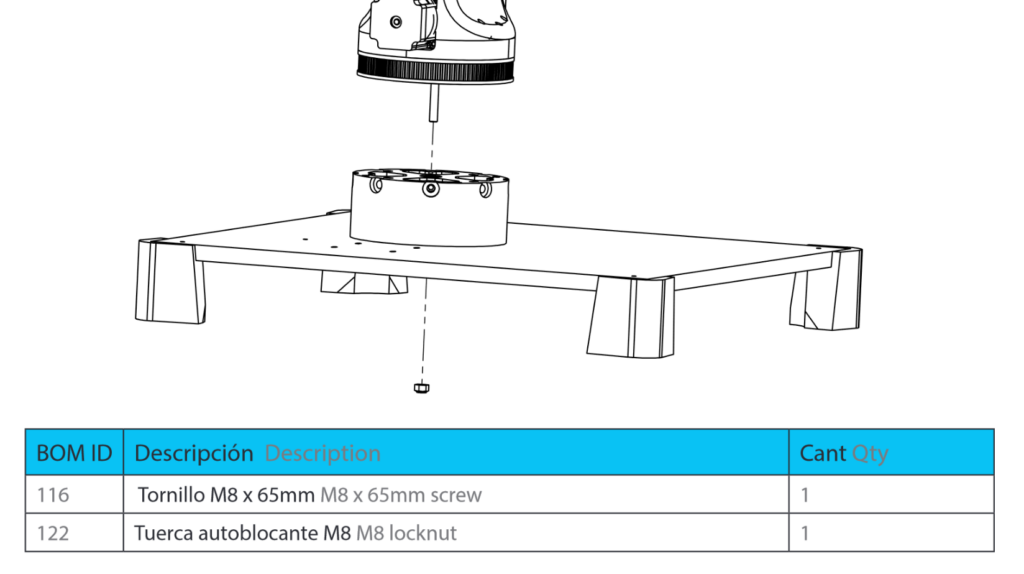
Step 5
As in step 4, there was no problem assembly this part. I did not have the M3 x 8 mm screws, only some M3 x 10 mm. Unfortunately, you can’t screw the screws deep inside the motor, so I had to rasp the 2 mm off from the screws. So there is a need to be this exact screw.
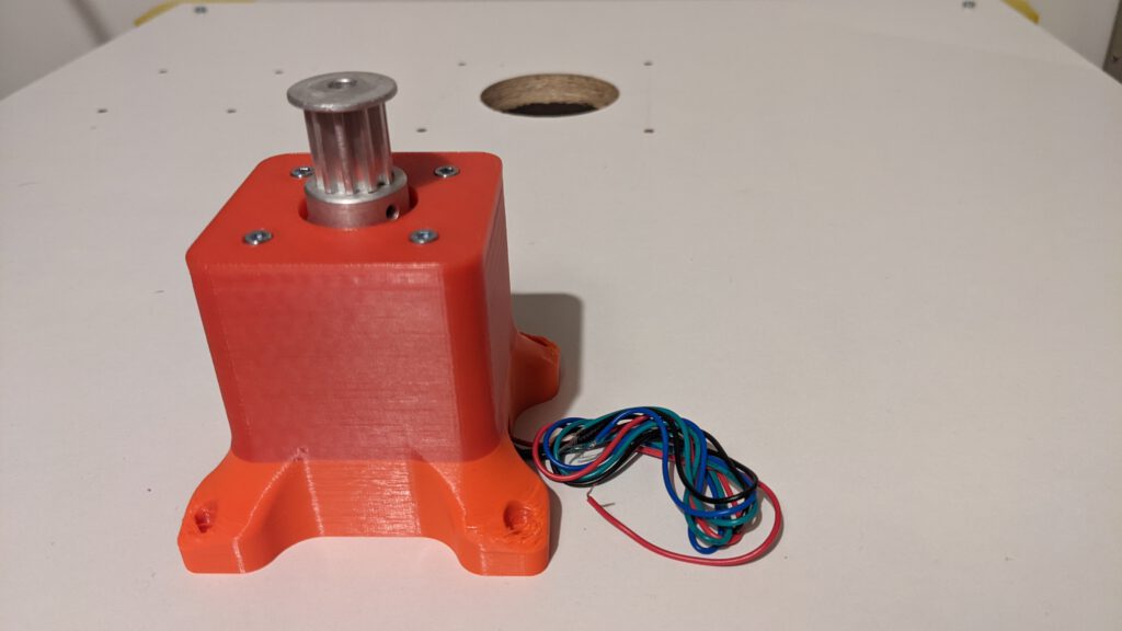
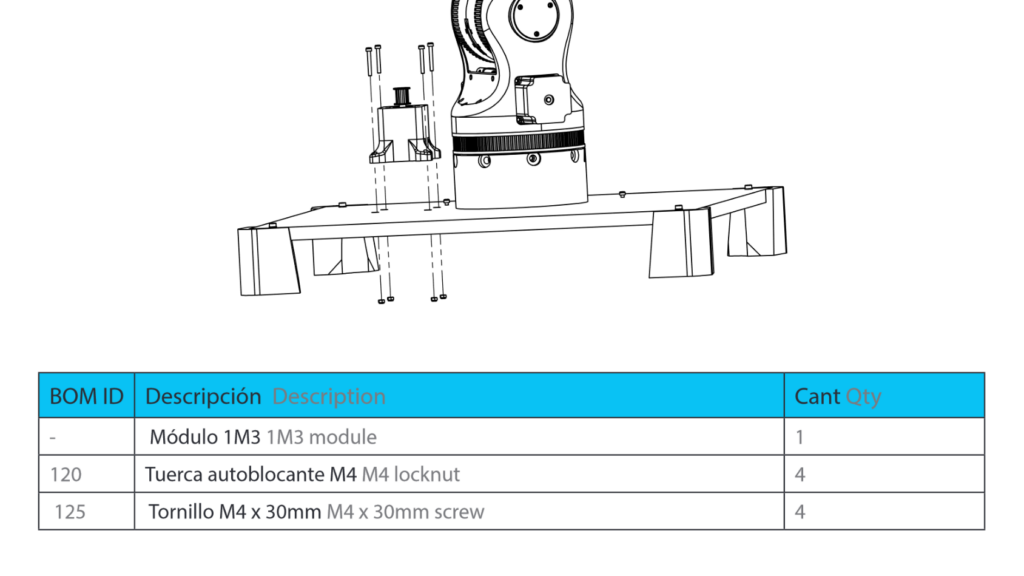
Step 6
In this step, we should install the motor and the arm to the base. But again like in step 5 I have not the right screws. My screws have the wrong head and do not fit into the 1M3 printed part.
I order some with a cylinder head, but they will not arrive for the release day for this post. I owe you this step. Furthermore, I ordered M4 x 40 mm and will use them in both parts. There is no need for me for the M4 x 30 mm any more in this part.

Be aware of the orientation for the outgoing cable from the motor case. The cable should be oriented, shown in the picture.
Result

Even this is not mounted on the base. This is the result you should have. The hole basement together! Great – See you next week with the new building part!
I think you had the difficulties with the posts because you used M4 Screws / Nuts. In the CAD model, you can look up that you should use M5x30 Screws and M5 Look Nuts instead. I’m certain if you change the screws, you did not need the tooth sticks anymore!
Regards,
luckyfu
Thank you a lot. You are right. I have changed the screws and will edit this post soon