At first, I would not have included this into the weekly updates because I thought it should be trivial to screw the parts onto the plate. But I had some difficulties doing it, and I think this are the more important parts of this series. A reader pointed out that I made a mistake in the privies part. I will sort the mistake with this post out, too. So, the agenda for this post is first screwing the remaining parts onto the wood plate and second correct the error from last time.
Step 6 (Again)
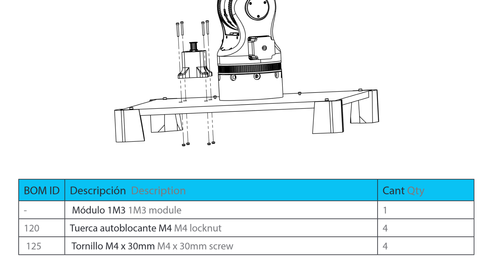

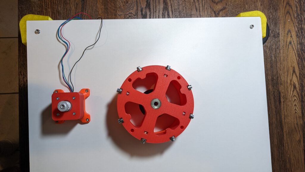
Mounting 1M2 and 1M3
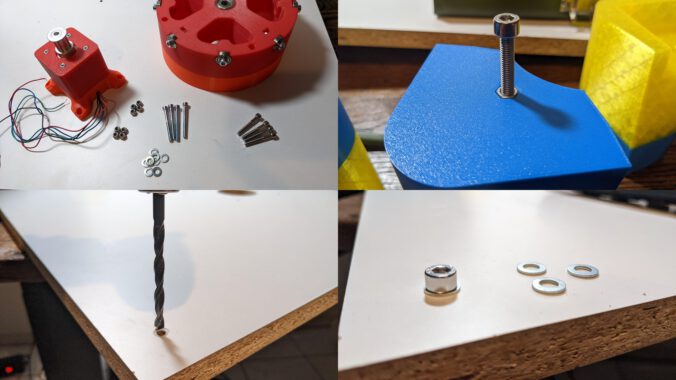
In part 7 in this series, I have not the screws needed to mount the 1M2 and 1M3 on the baseplate. My 1M3 is not good on the holes for the screws. So, I after bore the holes to fit the screw heads inside the holes.

After I after bored the holes, the result is much better. This step should not be necessary if your print comes out better than mine.
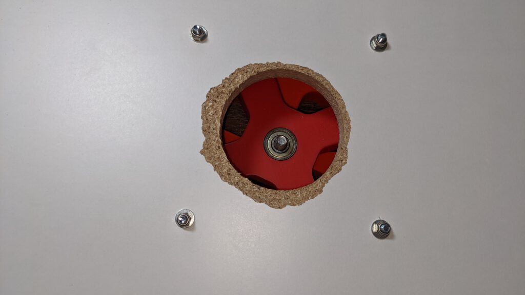
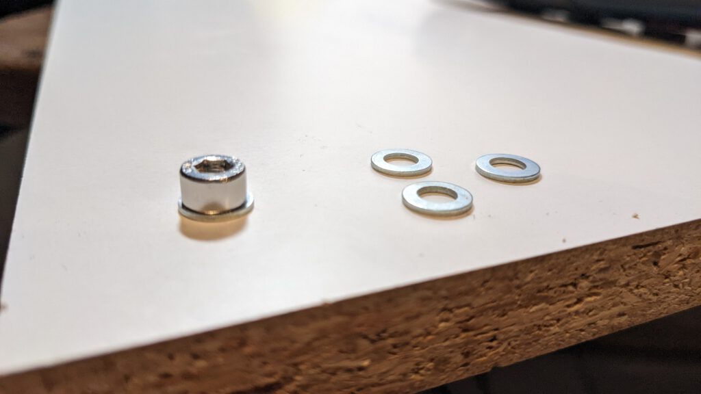
I used a M4 washer to distribute the pressure from the nuts on the wood plate. On this image, you can see the turn-out part from the hole saw. I did not drill the hole from both sides. I only drilled from the upper side, so the downside has to turn out parts at the corners.
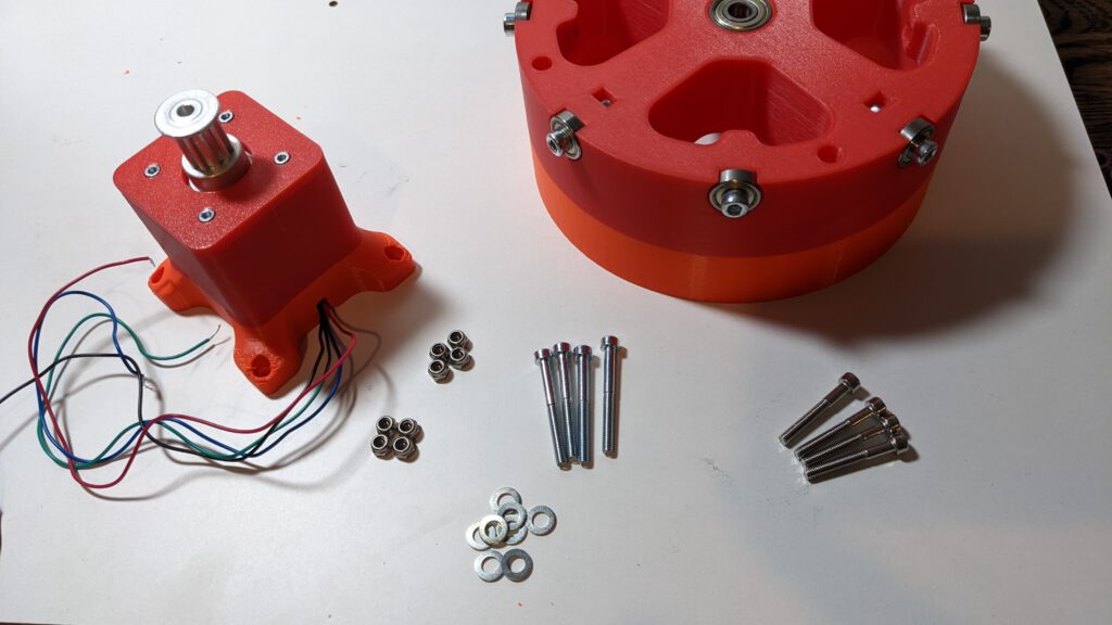
I had quite a hard time to fit the four screws from each part into the holes because the holes drilled into the wood weren’t precise enough.
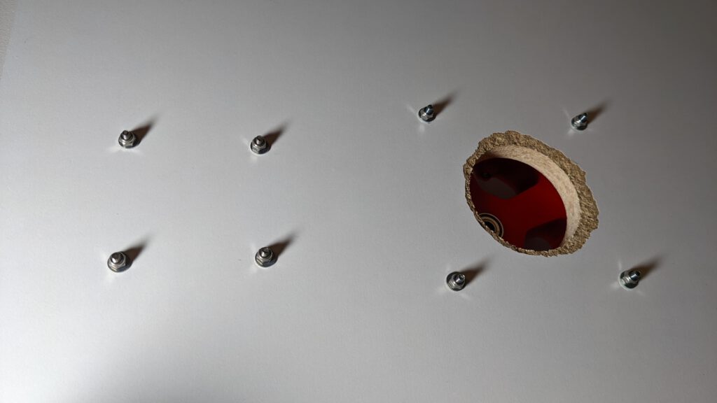
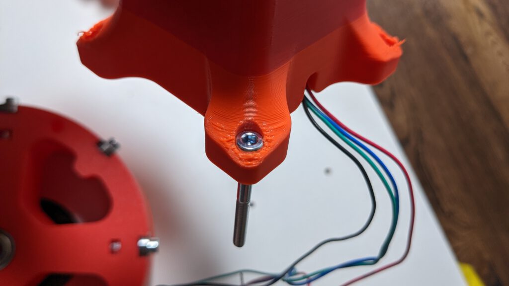
be aware of orientation from the cable. For a proper cable management, it is necessary that the cable is orientated as shown in the picture.
Step 7
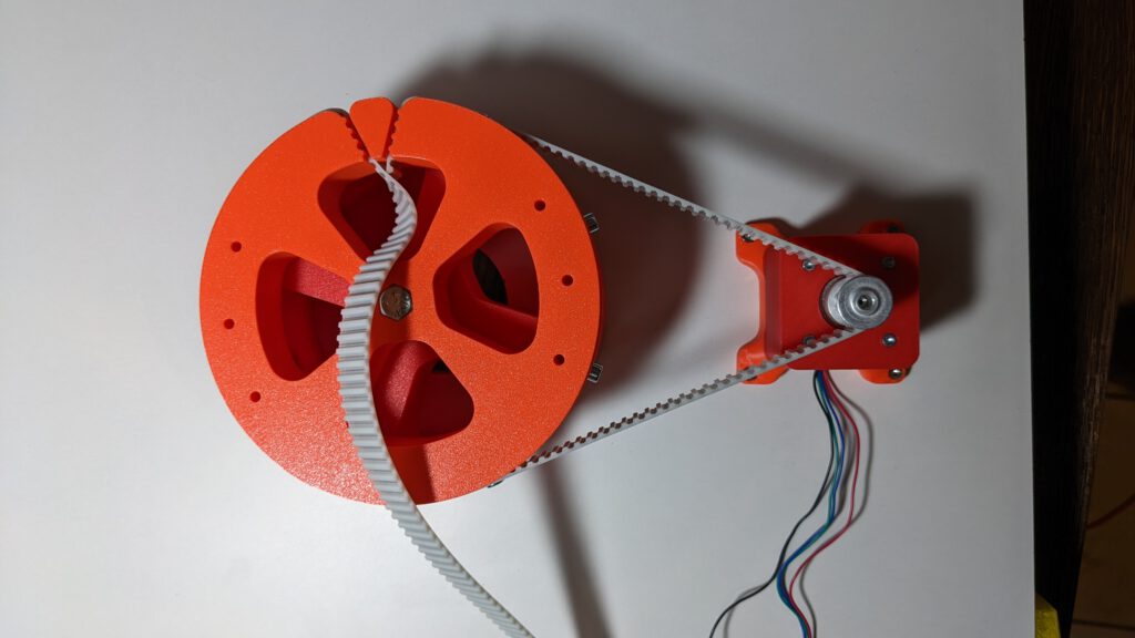
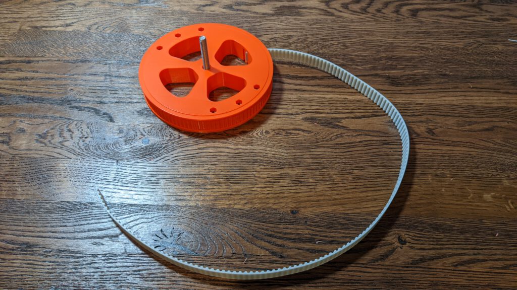
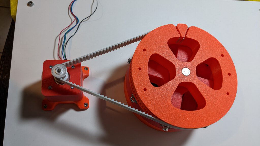
Mount the belt. I purchased a 2 m long belt and I tested the needed length. I inserted the belt like in the picture shown. Then I marked the point at the end where I have to cut the belt.
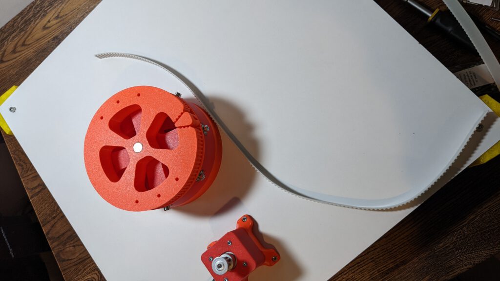
After the cut, I reinserted the belt, I had the finished result for this step. Insert the 6 M4 locknuts in this step, or you have to install the belt later again.

Step 8
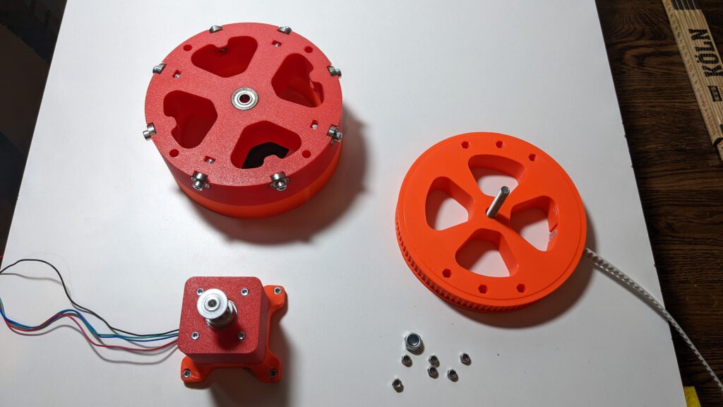
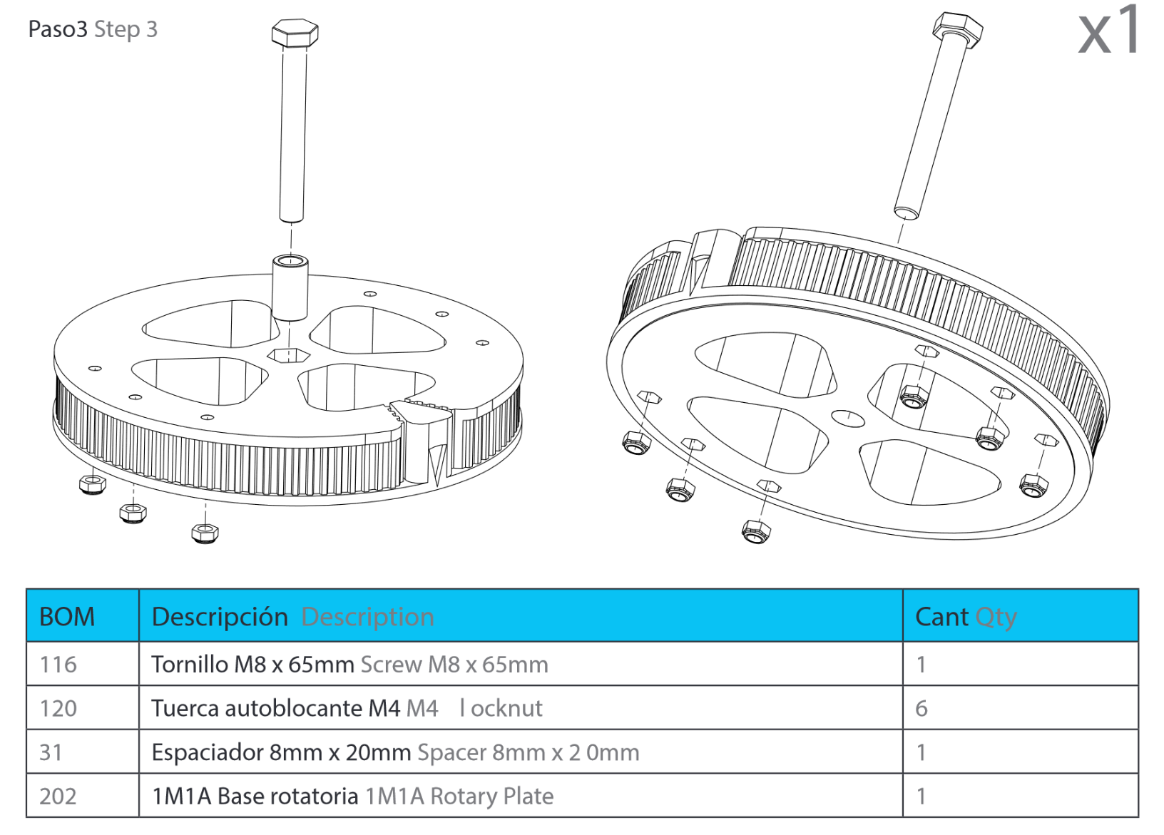
In this step, we’ll insert the 6 M4 locknuts into the 1M1 module.
After you inserted the Nuts, you can put the hole baseplate in top of this part
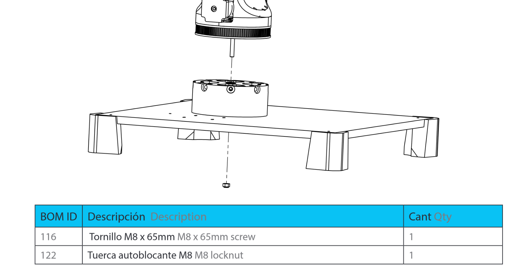
Now you can install the M8 Locknut on the M8 Screw and finish this step. Now the only thing to do is to put the belt again on the 1M1 part.
Fix an error: Change base posts screws
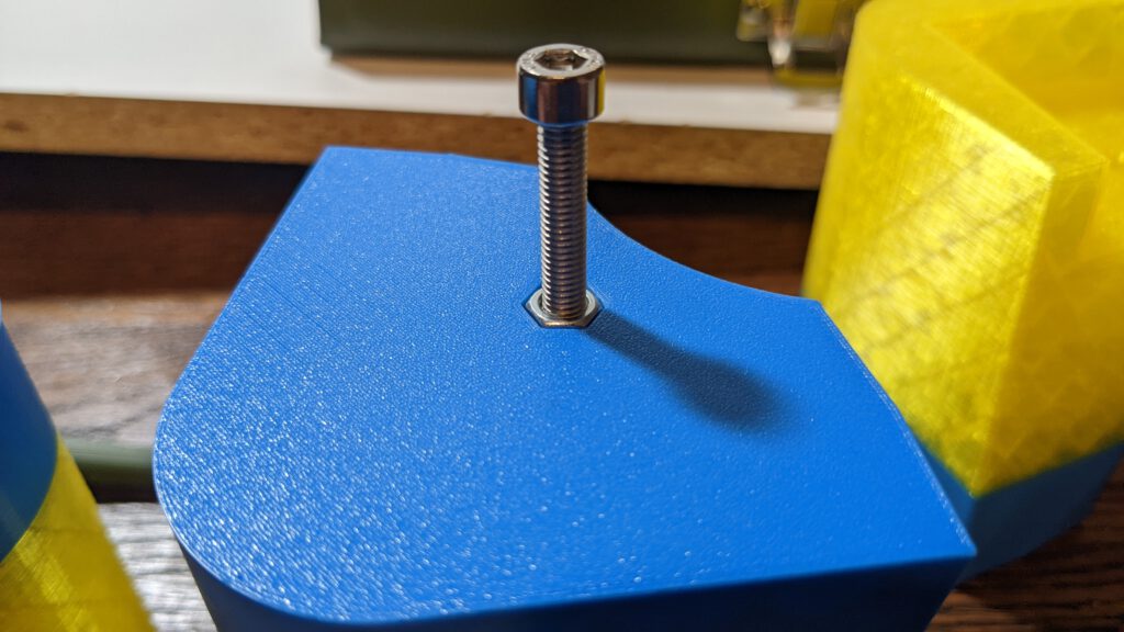
In the last part, I used M4x30 Screws for the base posts because I only looked up the hole diameter in the wood plate 3D model.

With M4 nuts, I had to use tooth sticks to install the screws. If I had used M5 nuts and M5 Screws, this would not be an issue. In the following picture, you can see that the M5 nuts fits perfectly in the base post.
To resolve the issue, I had to after drill the 4.3 mm holes with a 5.3 mm drill.
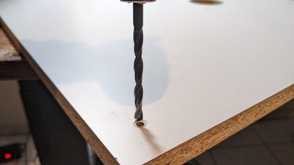
Thereafter, I used M5 nuts, washer and a M5 x 30 mm screw to assembly the posts again to the wood plate.
Leave a Reply