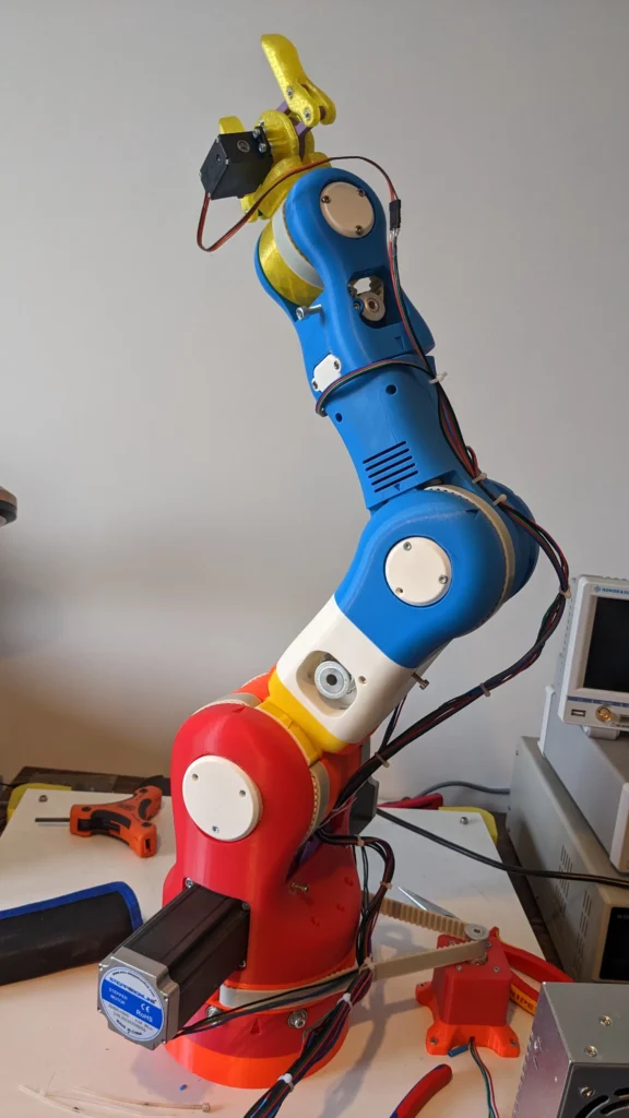
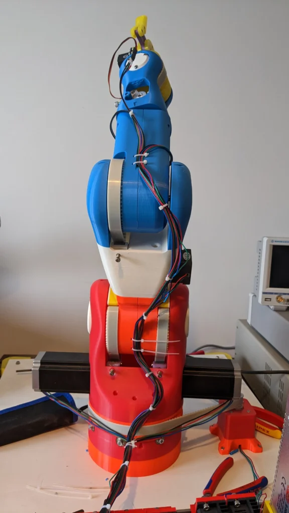
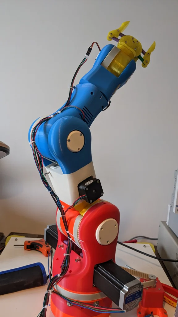
First, a little bit of definition. In the image below, the motors have now numbers according to its position.
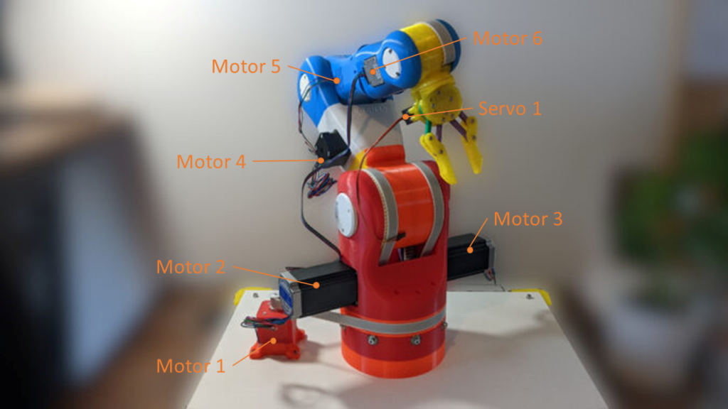
Now we can talk about a specific motor. In the third part of this series, I have mentioned the motor types. To refresh this bit of Information, you can have a look in the following table.
| Motor Nr. | Type | Torque | Current | Voltage |
| 1 | 42BYGHW609 | 0,4 Nm | 1,68 A | 12 – 36 |
| 2 | 23HE454204S | 3 Nm | 4,2A | 24 – 48 |
| 3 | 23HE454204S | 3 Nm | 4,2A | 24 – 48 |
| 4 | 17HS19-1684S-PG5 | 4 Nm | 1,68A | 12 – 24 |
| 5 | 42BYGHW609 | 0,4 Nm | 1,68 A | 12 – 36 |
| 6 | B089Y48SWK | 0,21 Nm | 1A | 12 -24 |
Now we know the specification for the motors. In the next step, we will “bind” each motor to one motor driver.
BOM
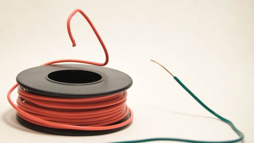
Only cables and cable ties are needed for this part
Microcontroller to Drivers
NOTICE: I installed the drivers first to the uC, but in retrospect I should have installed the motors to the drivers first. All the small cables needed to use the drivers are disturbing during the installation from the engines.
Therefore, we can label the wires from the motor drivers to the microcontrollers. The TB6600 and the DM556 Driver have three incoming signals, Enable, Direction and Step.
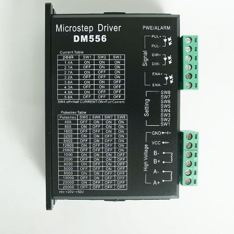
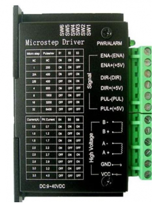
We have four TB6600 and two DM556. Each driver is attached to one motor. Be aware that the TB6600 Drivers have the negative signal on the first, third and fifth input and the DM556 drivers have the negative signal on the second, fourth and sixth input.
| TB6600 1 | TB6600 2 | TB6600 3 | TB6600 4 | DM556 1 | DM556 2 | |
| Motor No. | 1 | 4 | 5 | 6 | 2 | 3 |
| Enable | E1 | E4 | E5 | E6 | E2 | E3 |
| Dir | D1 | D4 | D5 | D6 | D2 | D3 |
| Step | S1 | S4 | S5 | S6 | S2 | S3 |
In my case, I went from left to right with the numbering of the motor drivers.
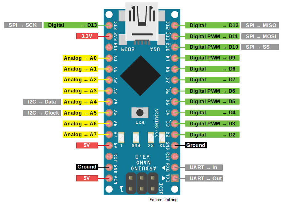
The Pinout from our microcontroller is shown below. For the drivers, we will use up almost all digital pins D2 – D13, except pin D5.
| Arduino Pin | Type | Driver Label |
| D2 | E1, E2, E3, E4, E5, E6 | |
| D3 | D1 | |
| D4 | S1 | |
| D5 | PWM | |
| D6 | PWM | D4 |
| D7 | S4 | |
| D8 | D5 | |
| D9 | PWM | S5 |
| D10 | PWM | D6 |
| D11 | MOSI | S6 |
| D12 | MISO | D2, D3 |
| D13 | S2, S3 |
Drivers to Motors
Connecting the NEMA 23 engines
The LED cable is only rated for 3.2 A. The only engines that exceed this limit are the two NEMA 23 engines.
According to the blog post, we can use an AWG 18 cable instead.
Driver settings
The settings are simple for the drivers. We just need to limit the peak current. From the following table, you can see which motor needs which settings with which driver.
| Motor No. | Setting | Driver |
| 1 | 011110 | TB6600 |
| 2 | 01001110 | DM556 |
| 3 | 01001110 | DM556 |
| 4 | 011110 | TB6600 |
| 5 | 011110 | TB6600 |
| 6 | 011101 | TB6600 |
Servo to microcontroller
GND and 5V of the servo are connected directly to GND and 5V of the Arduino. The PWM pin of the servo is connected to GPIO pin D4 on the arduino.
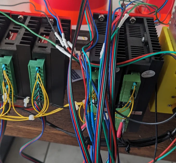
Clean Up
Now fix the cable accordingly with cable ties
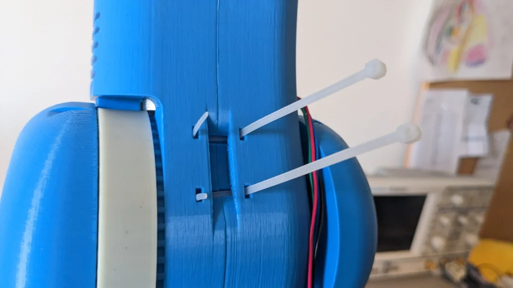
With a few cable ties you should also come to my result
In the next tutorial, we will flash our first test program on the Arduino
Hey,
Great you’re still on this project, it has been joy to follow it 🙂
I’m starting this journey too.
Thanks for your feedback. 🙂 The project is more time-consuming than I thought from the beginning. Which is why there is currently less to this project (studies and such). We can gladly work together on this project.
Habt ihr weitere Ergebnisse?
Hallo ich habe mir den moveo auch gebaut bzw bin noch dran .
Gibt es mittlerweile eine fertige Marlin datei ?
Ich versagen bei der Einstellung der Servo bzw des zweiten Extruder Ausgang
Thank you for your interest in the project. So far, I am still writing the test software and could not take care of the firmware yet. I can’t provide you a date yet because I’m working on my master’s thesis in parallel and it has a higher priority for me. I ask for your understanding.
I’m planning on building this project. I’m new to 3D printing and I imagine there needs to be enough wall thickness for the heated inserts and enough to make the arms structurally sound.
For 3D printing, what wall or perimeter thickness did you use? Infill type?
Thank you for your interest in this project. I used the following: layer height: 0.2 mm Material: PLA Infill: 15%. You can find more information in the readme of the GitHub repo 🙂
I haven’t chosen a specific wall strand, which is usually selected directly with the infill or the layer hide. I would recommend that you keep this default value as well