In this post, we’ll install the brain for our MOVEO project. Instead of the teensy, we’ll use an Arduino because it is for now better to handle. In a future post, I’ll potentially change the processing unit, but for now, the Arduino will do an impressive job.
BOM
With this post, I introduce a new BOM-ID feature. The original BOM-ID’s have the pattern 0xx for Components, 1xx for fasteners and 2xx for 3D-printed parts. I designed in the series some parts and struggle since with a BOM-ID for my parts.
I’ll copy the schema 0xx, 1xx and 2xx, but my features will have a leading 1.
- 10xx: Components
- 11xx: Fasterens
- 12xx: 3D-Printed parts
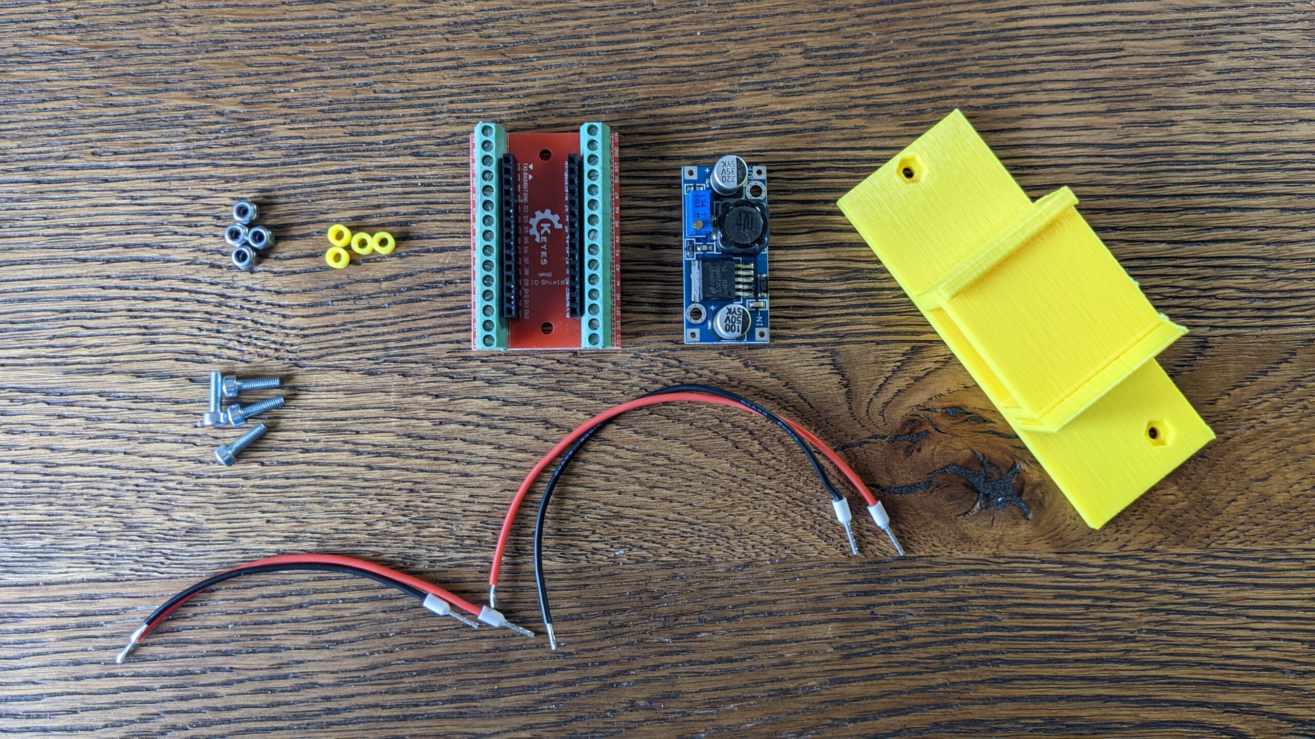
Here is the first BOM with the new system.
Step 1: Installing the breakout board

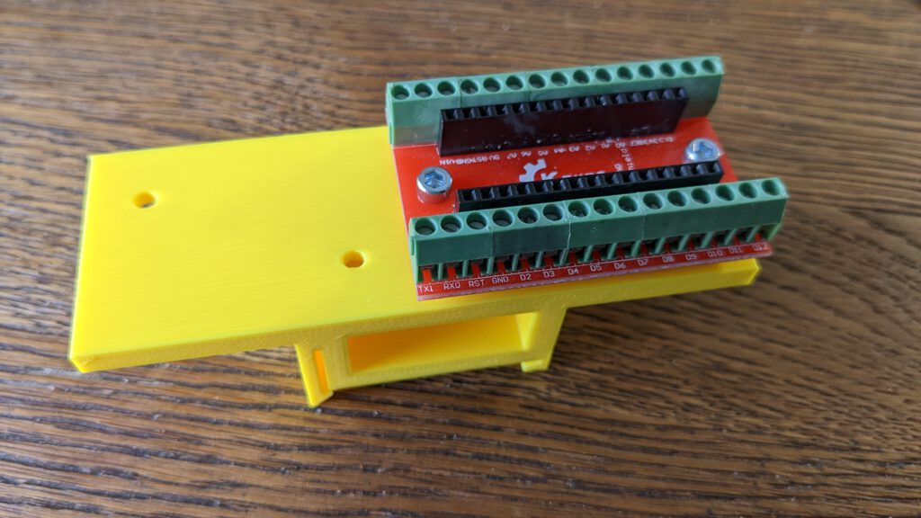
This part is straightforward. Just install the Arduino breakout board on the brackets with the M3x10 Screws. The Vin pin should be on the bottom-left side.
WARNING: Do not insert the Arduino yet!
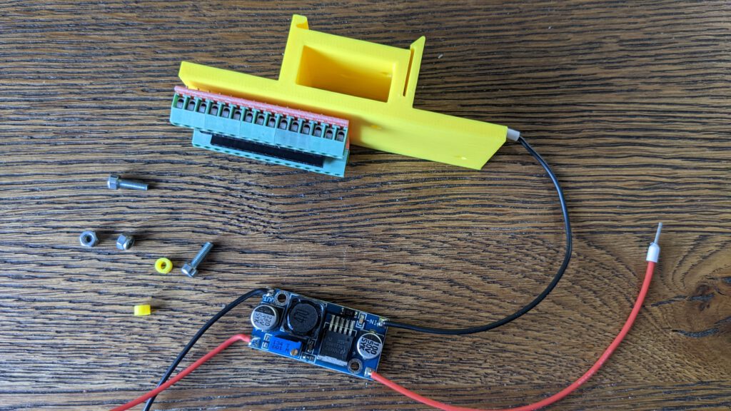
Step 2: Prepare DC – DC converter
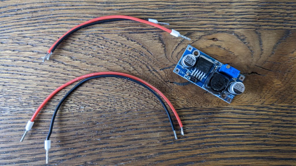
I’m cutting the 15 cm cables in one 5 cm and two 10 cm pieces. On one of each side from each cable, I used end splices. Then I soldered the 10 cm cable to the voltage IN side and the short 5 cm long cable to the voltage out connectors.

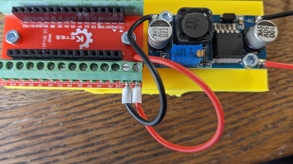
Step 3: Install DC-DC converter
Install the DC-DC converter like the breakout board. Notice, that the voltage Out-Side should look towards the breakout board.

Now connect the DC-DC-Converter output cables with Vin and Ground.
| Arduino Pin | DC-DC Converter |
| Vin | V+ / Vcc |
| GND | V- / GND |
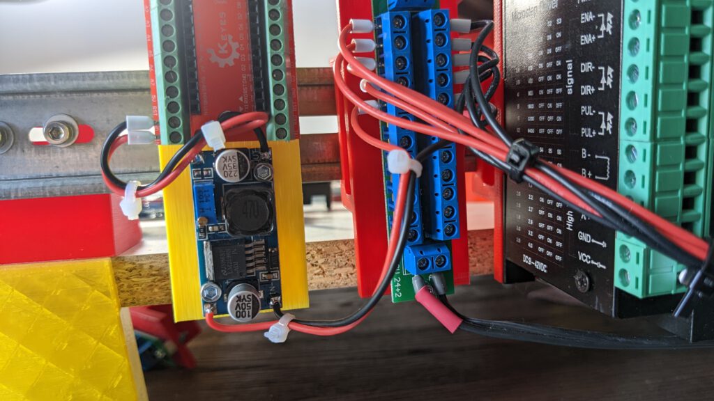
Step 4: Installing on DIN Rail
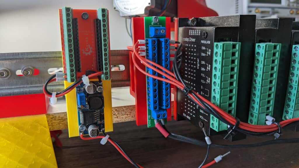
Install the bracket on the DIN Rail. Connect the cables to the power distributor.
Step 5: Calibration DC voltage
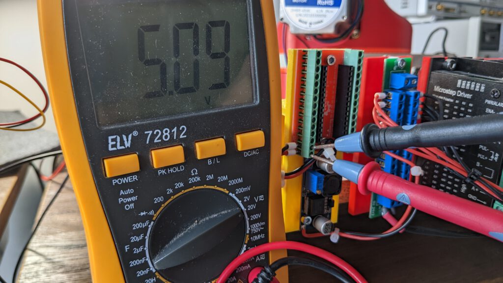
Now connect a voltage meter to the GND and Vin pins. You can rotate the screw in the potentiometer to set the voltage to a value near 5V. I’m going to use 5.1V to power the Arduino.
Step 6: Arduino
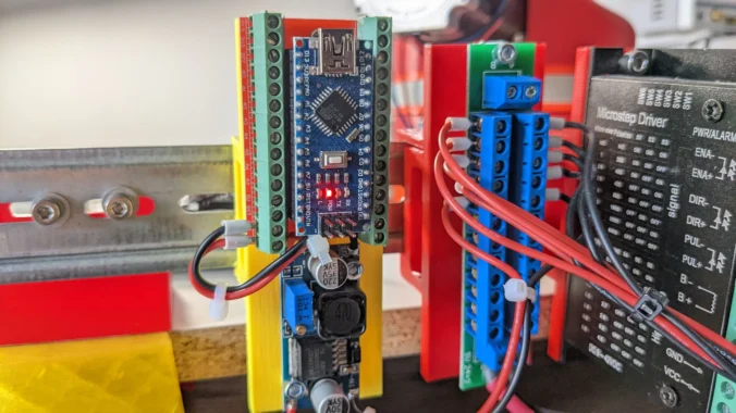
Insert the Arduino and power up the PSU. The Motherboard is now working!

With the Arduino Nano do you get forward and inverse kinematics. Will the tool move in straight lines between locations? Or is the motion more point to point in joint mode.
Is there a GUI? how is the arm moved, game-pad, joystick, or keyboard?
I have not yet implemented inverse kinematics. There are projects that provide a GUI but I haven’t tried them myself.