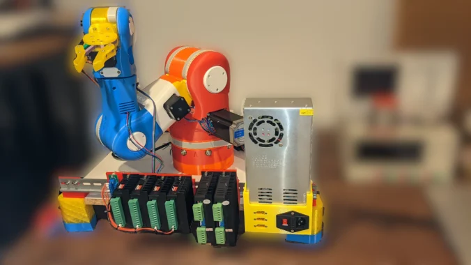
I want to create a housing for the PSU, so we don’t have to mess with open 230V / 110V wires. I decided to use a default IEC320 C14 connector for voltage in and three XT60-Connectors for voltage out. The PSU will be mounted on the DIN-Rail too. Two of the three outputs are direct connected to the DM556 motor drivers. The third is connected to the PD (power distributor). With this, we have a clean round thing, to power up our robot.
Design


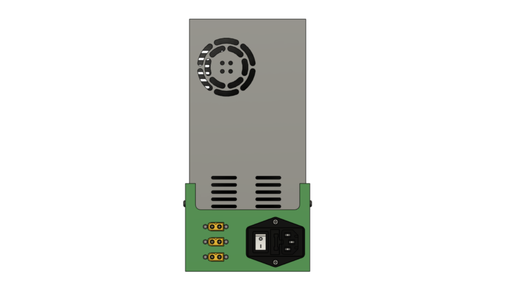
The PSU is mounted on the DIN Rail. The design is inspired from the Rep Rap PSU Module. The main differences are the connectors for the outgoing current.

Two from the yellow XT60E-M connectors are for the TB560 drivers, and one is for the Power distributor installed in the last post.
The models are in the git repository as STL files.
- PSU Case (PSU Case v<XX>.stl)
- DIN PSU Rail Bracket (DIN PSU Rail bracket v<XX>.stl)
BOM
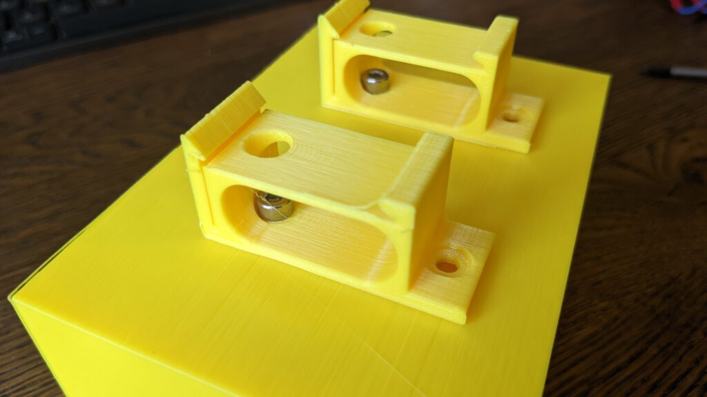
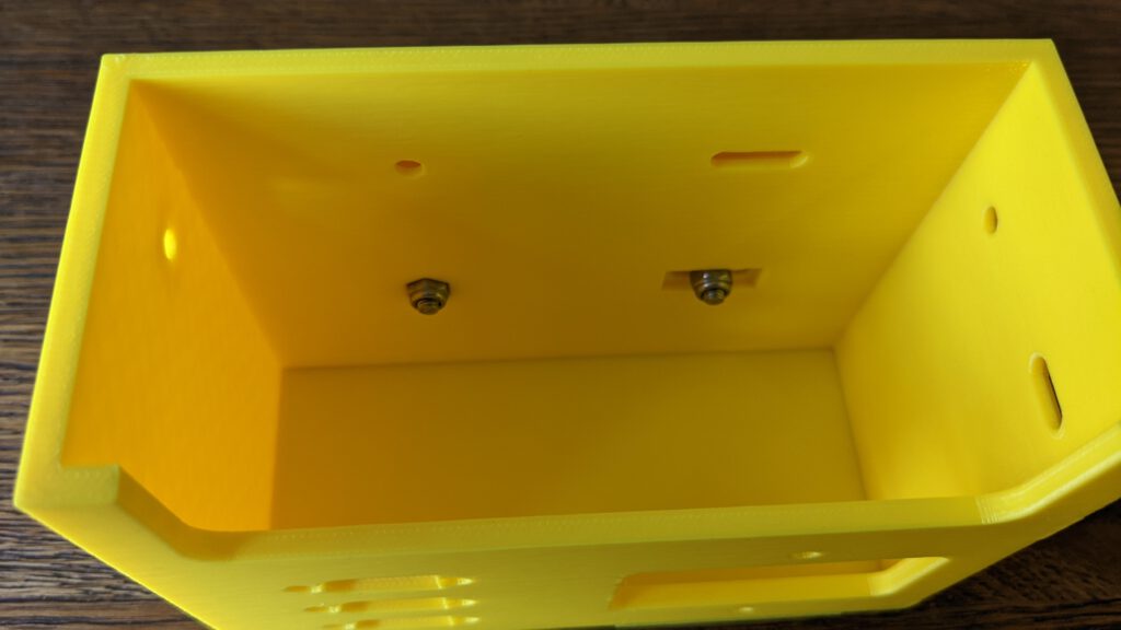
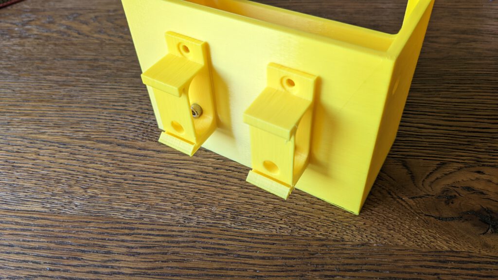
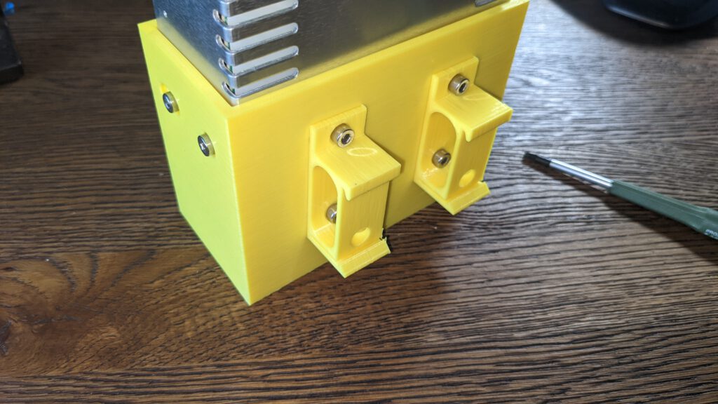
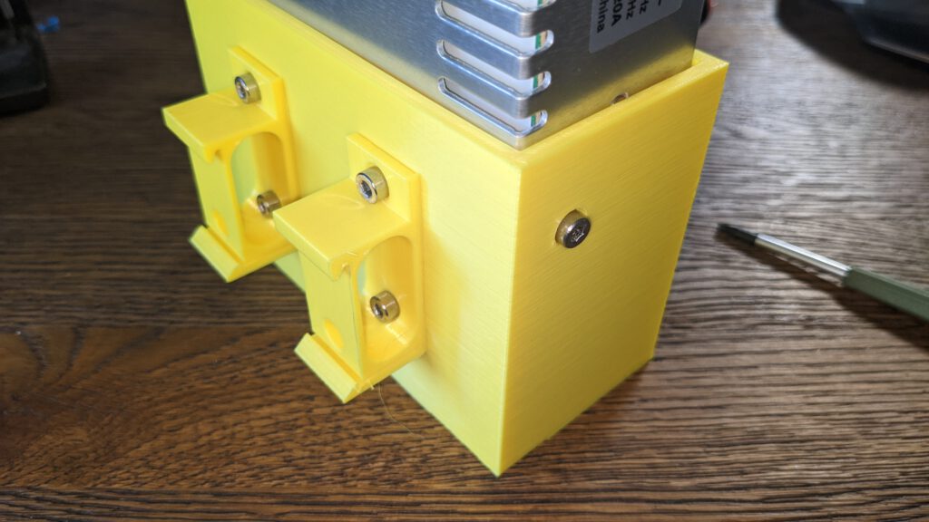
Step 1: Install the Brackets
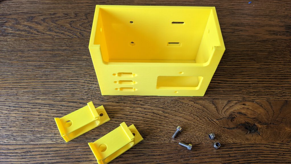
Insert the two Locknuts in the lower holes for the brackets. After this, screw them tight with the M4x10 screws.
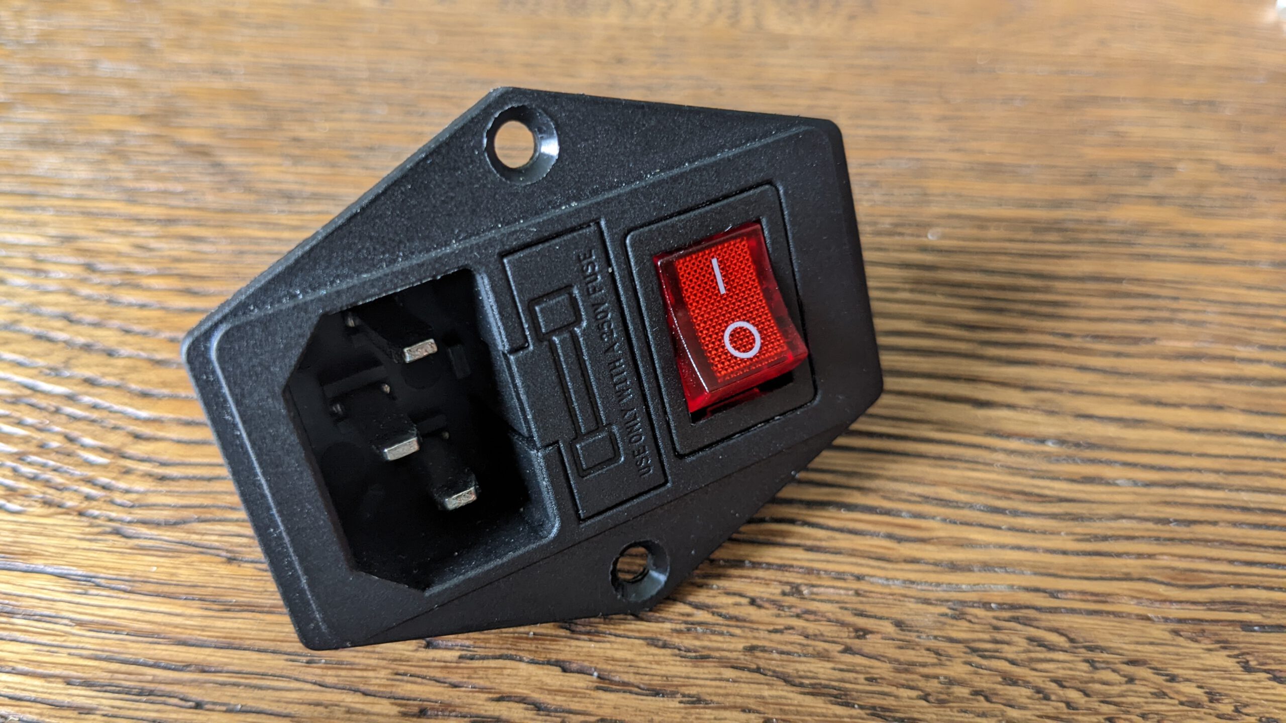
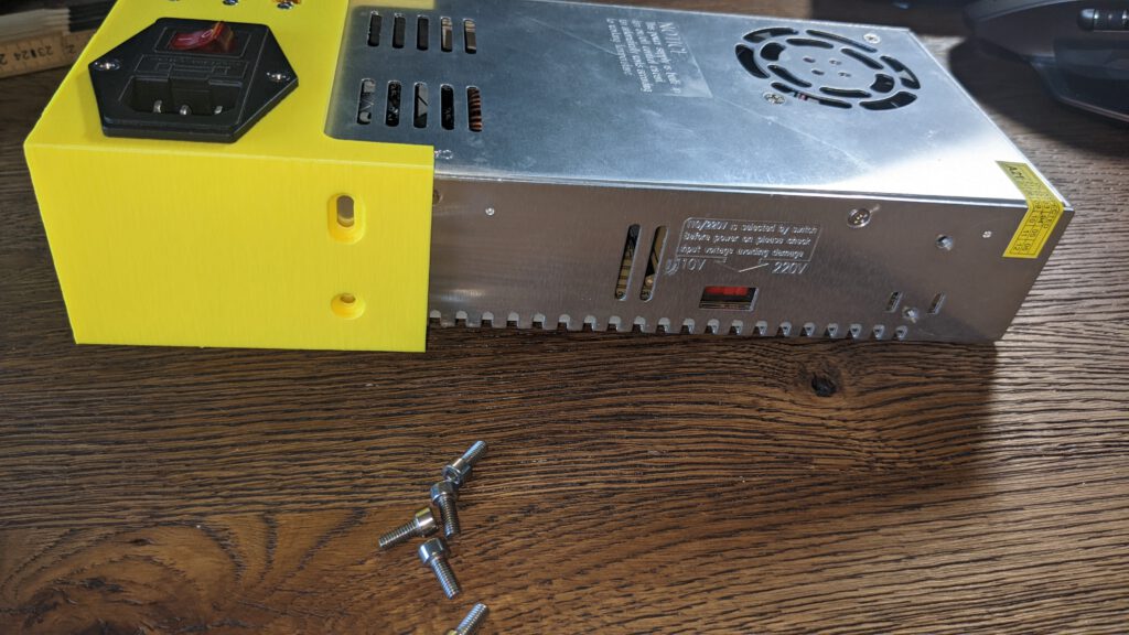
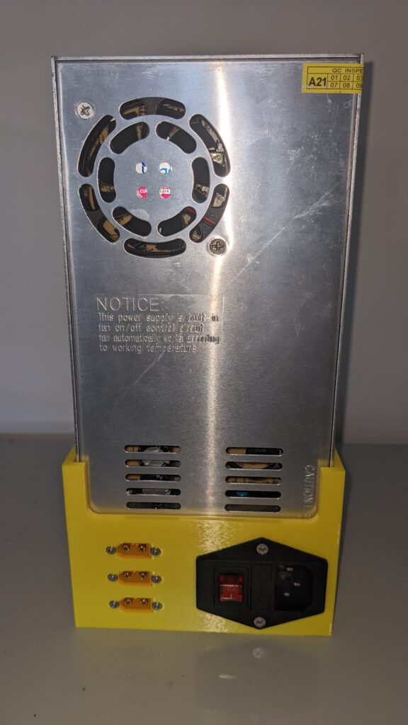
Step 2: IEC320

To install the IEC320 C14 connector, please follow at first the IEC320 C14 wiring guide.
If you are following my guide, your result should look like the image below.
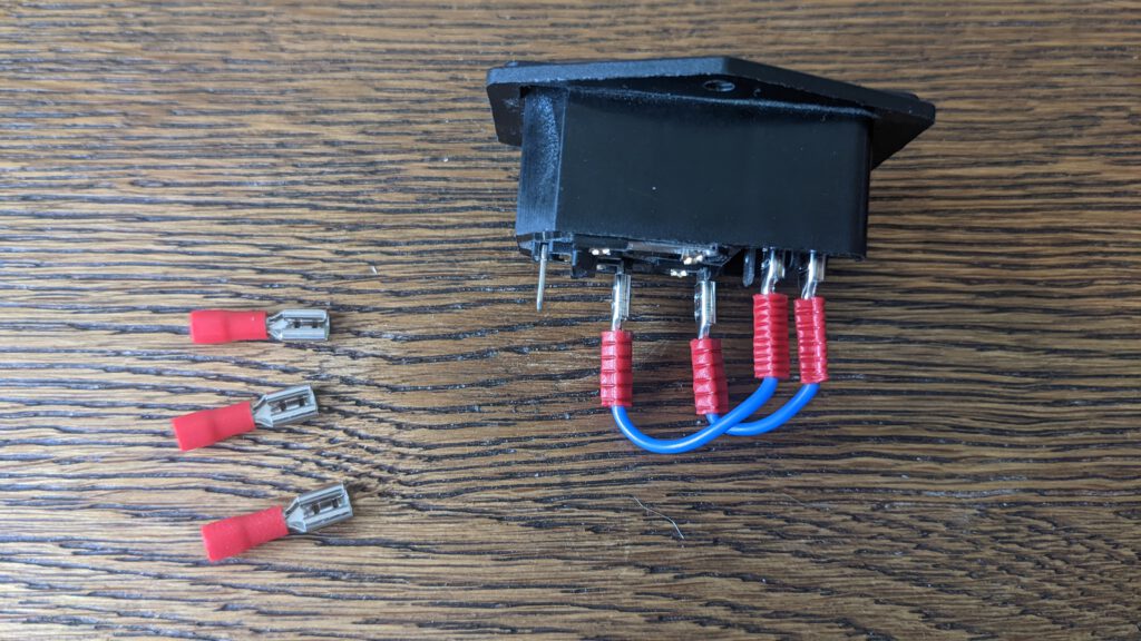
I used 15 cm long AWG20 cables for the connection between the PSU and the connector. For the connection, I used terminals to screw them tight later.
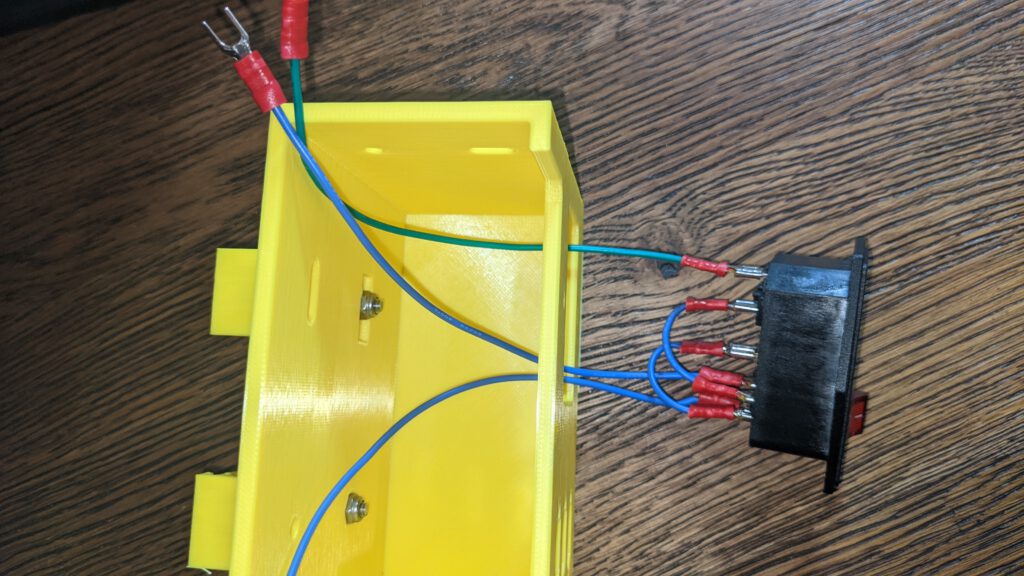

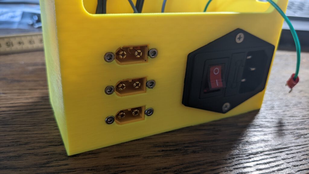
Then insert the IEC320 C14 plug into the hole and screw them in with the M3 countersink screws. Your result should look like the following.

Step 3: XT60 Sockets

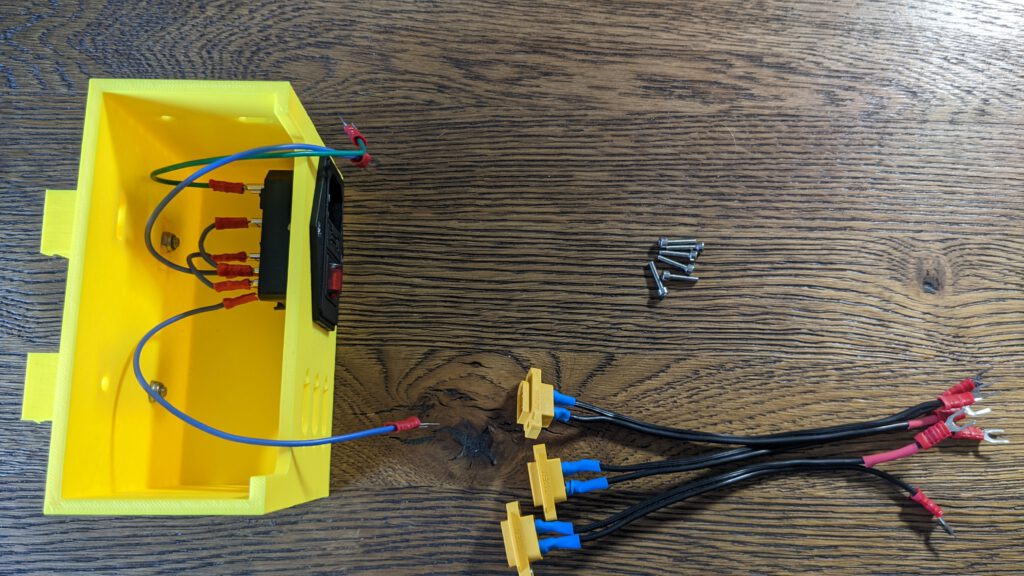
I soldered three of them with a 20 cm long AWG18 cable together. On the other end I pressed some terminals, too.
You need the six M2.5 screws to screw them into place.

After you screw all of them into place, you result should look like this.
Step 4: Wiring up the PSU
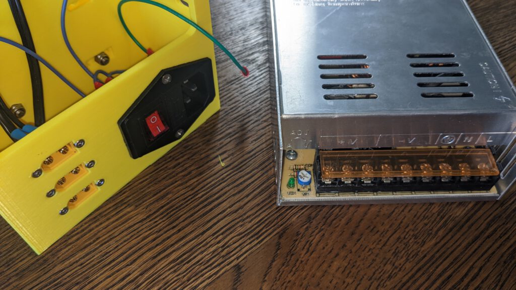
To wire up the PSU you have to connect Ground, Phase, and neutral from the IEC320 connector to the psu.
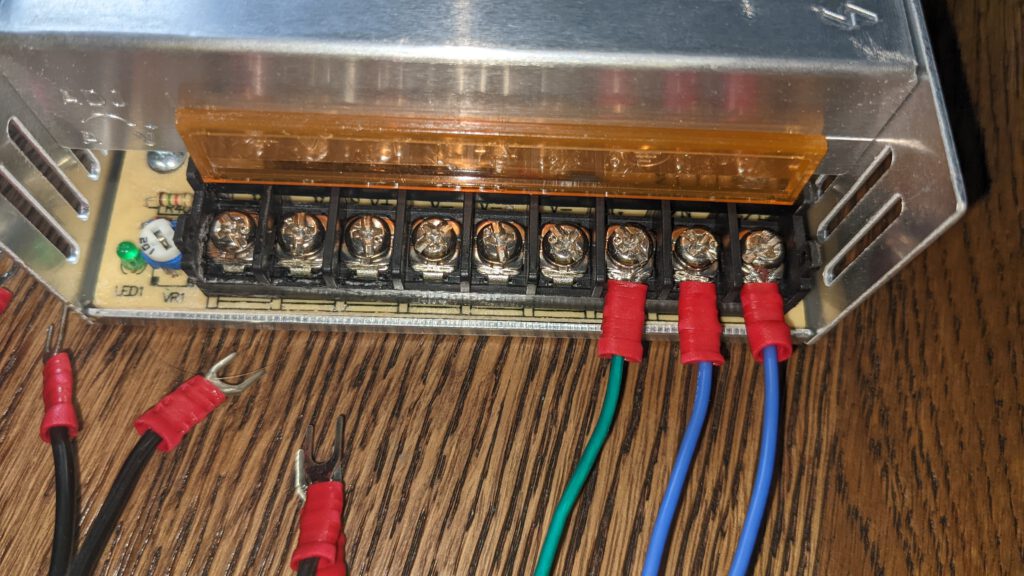
If the cables are mounted well, you can proceed with the cables from the XT60 connectors. Please note the right side is plus and the left three terminals are all GND.
Now you can secure the PSU with the M4x10 Screws, two on the right side, one on the left and two through the brackets.
Step 5: PSU on the Rail
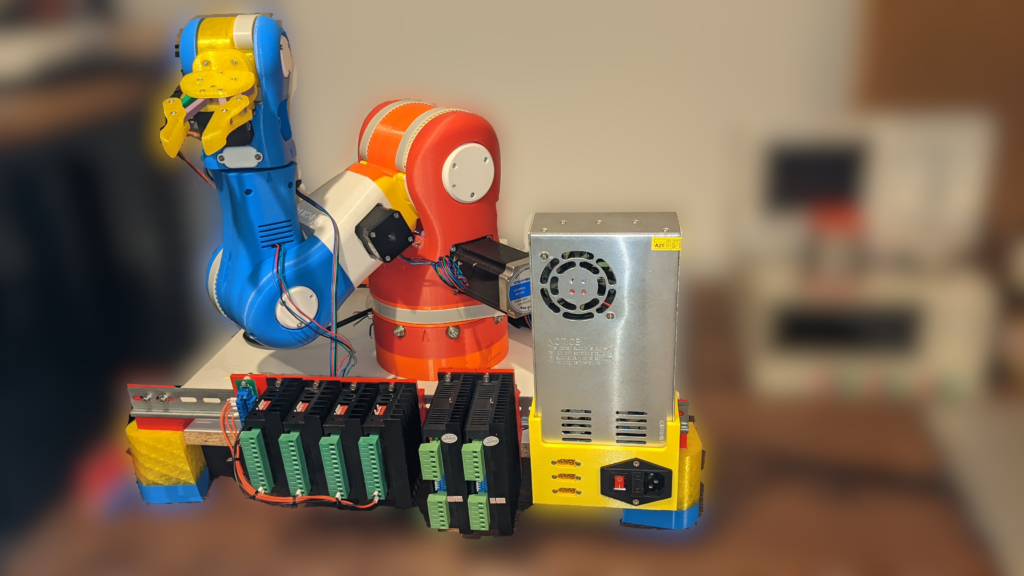
Followed by the last step: wire it up!
Step 6: PSU cable
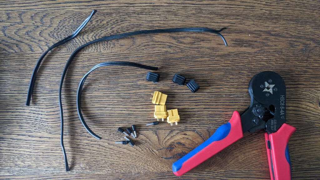
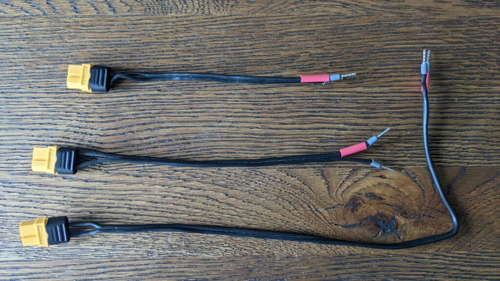
I created three cables with the following length
- 16 cm
- 20 cm
- 36 cm
All of they have the XT60 male plug on one side and ferrules on the other side. The 16 and 20 cm cables are for the DM556 Drivers, and the long 36 cm cable is for the power distributor board.

If you now turn on the PSU the board all green lights from all drivers should be , turned on, too!
Leave a Reply