The 4rd module comes with some issues, that we had to solve. The motor I chose did not fit inside the 4M1 part, and the bad print quality from my 4M1 part forced me to file some layers down. If you’re interested, stay tuned!
Preparation
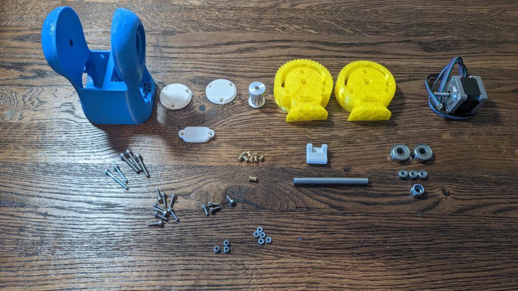
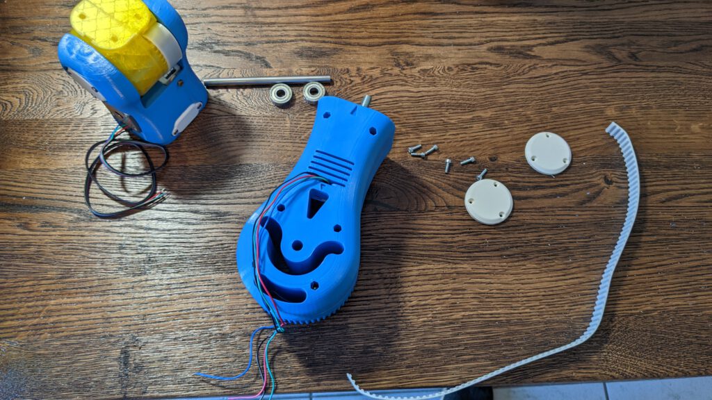
BOM for part 4
Tools
- HX4 Screw driver
- HX2 Screw driver (for the pulley)
- Solder Iron
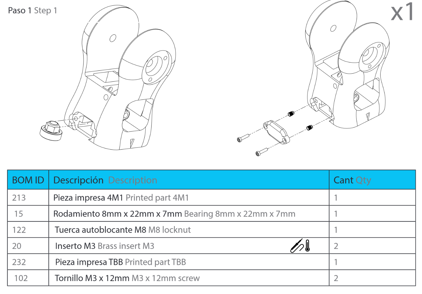
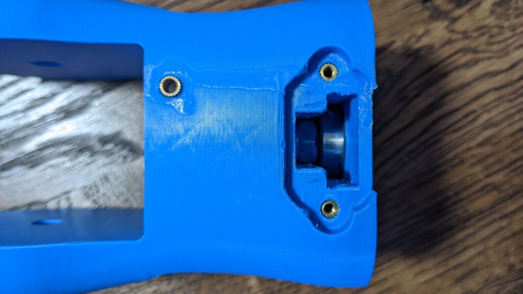
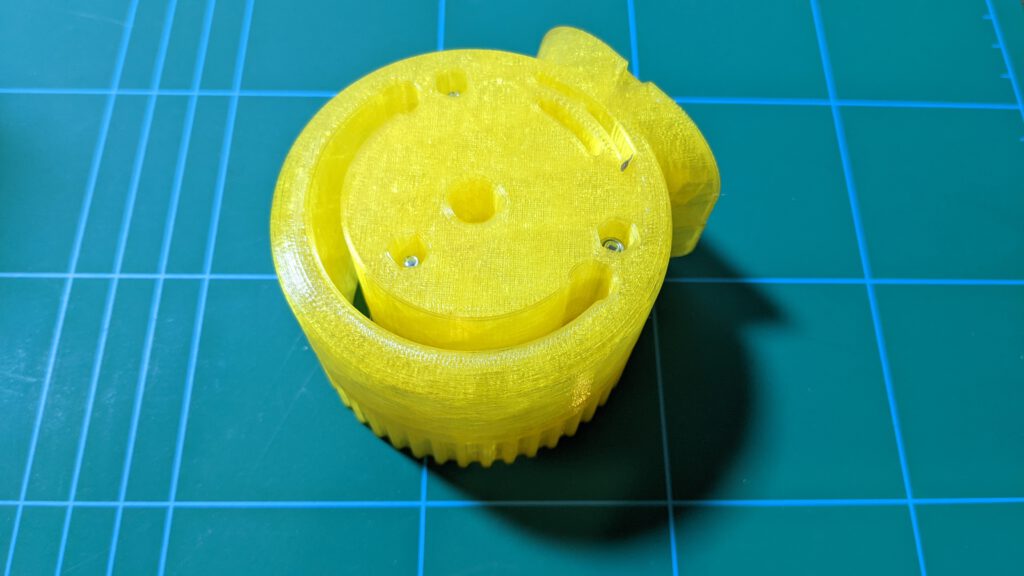
Step 1: Brass inserts
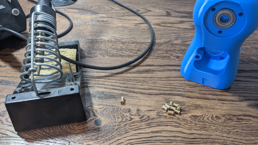
I heated the solder iron to 350 °C and pressed the inserts into the holes.


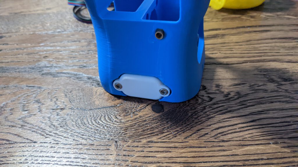
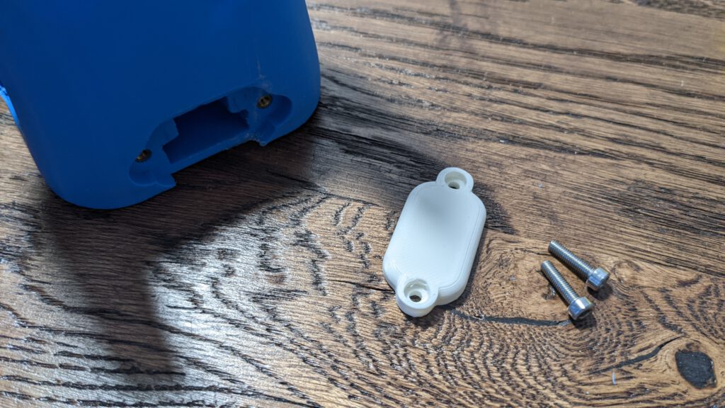
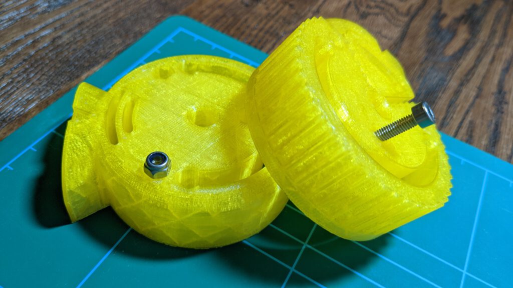
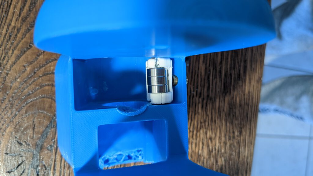
Step 2: Locknut
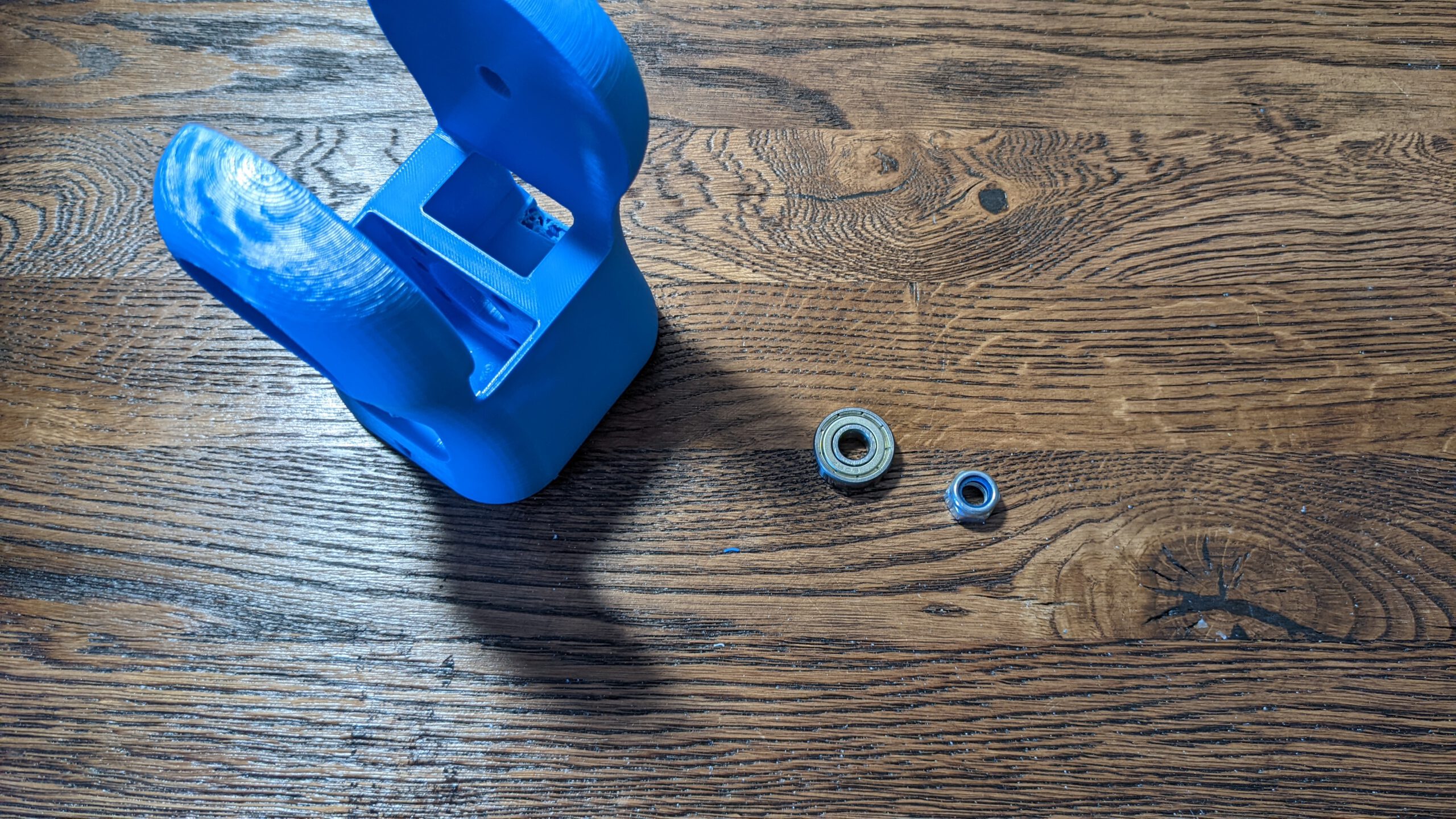
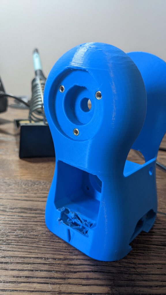
My 4M1 part is not perfect printed. I did not know how to print the hole for the bearings – with or without support material. I choose to print without support material, but unfortunately, the bearing does not fit inside the hole.
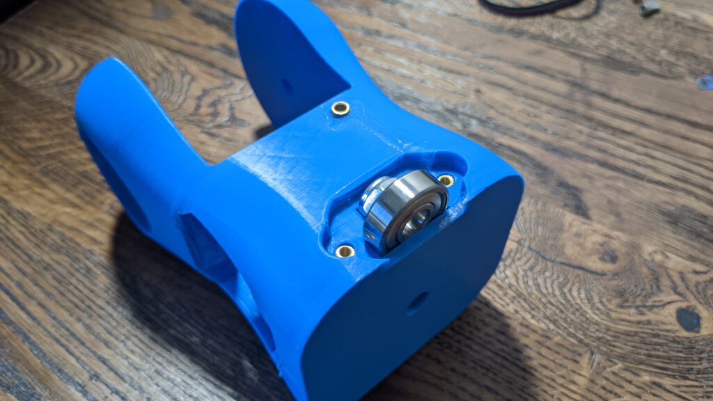
I had to file away some parts inside the hole. After that, the bearing fits inside the hole
The screw down the cover and this step is done
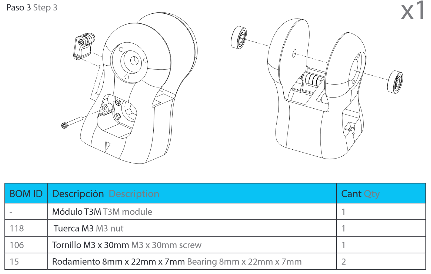
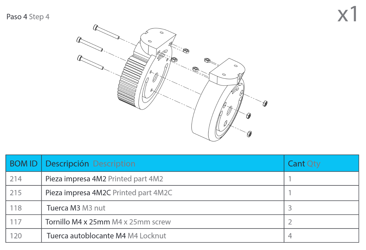
Step 3: 4M2 assembly
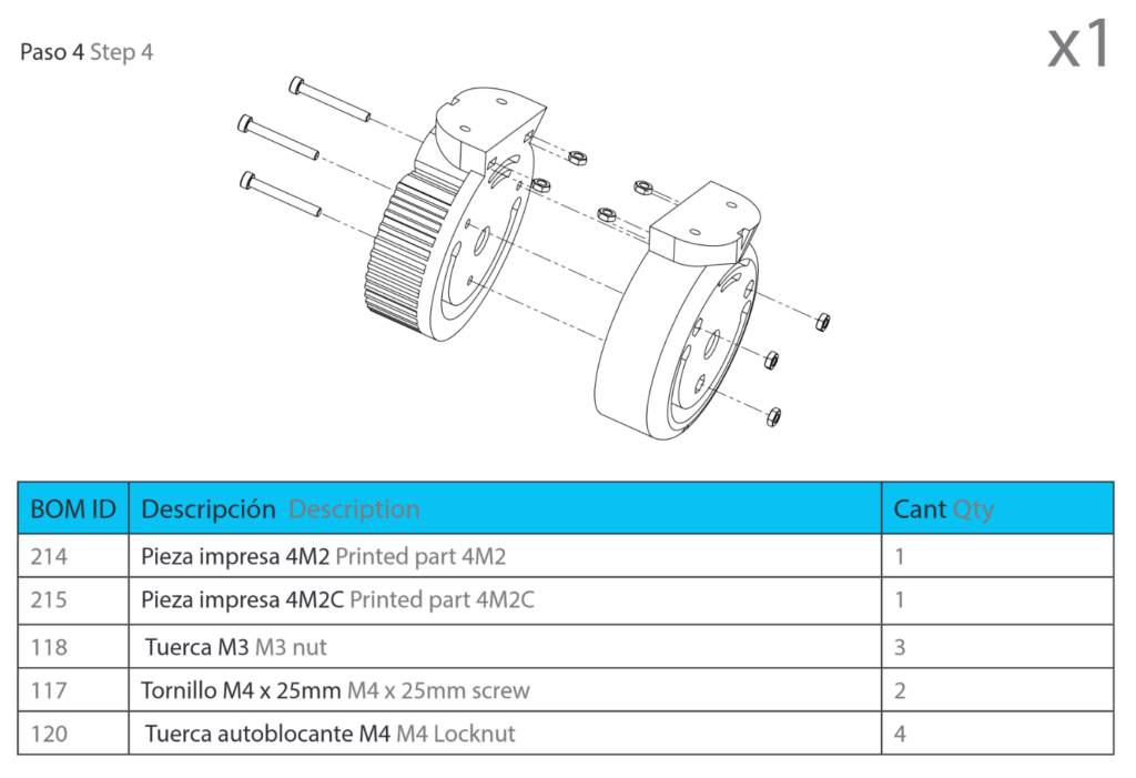
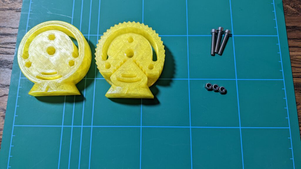
M4 is not the correct diameter. The Locknut is too big for the small hole, and the Screw does not fit into the hole from the 4M1C part.
The correct format is M3. We have to change the Screws from BOM ID 117 (M4x25mm) to 105 (M3x25mm). After the screw swap the you can easliy assembly both parts.
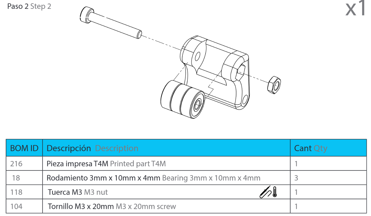
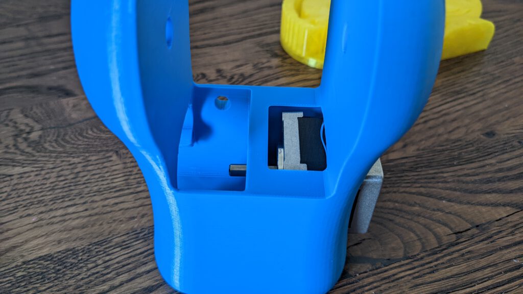
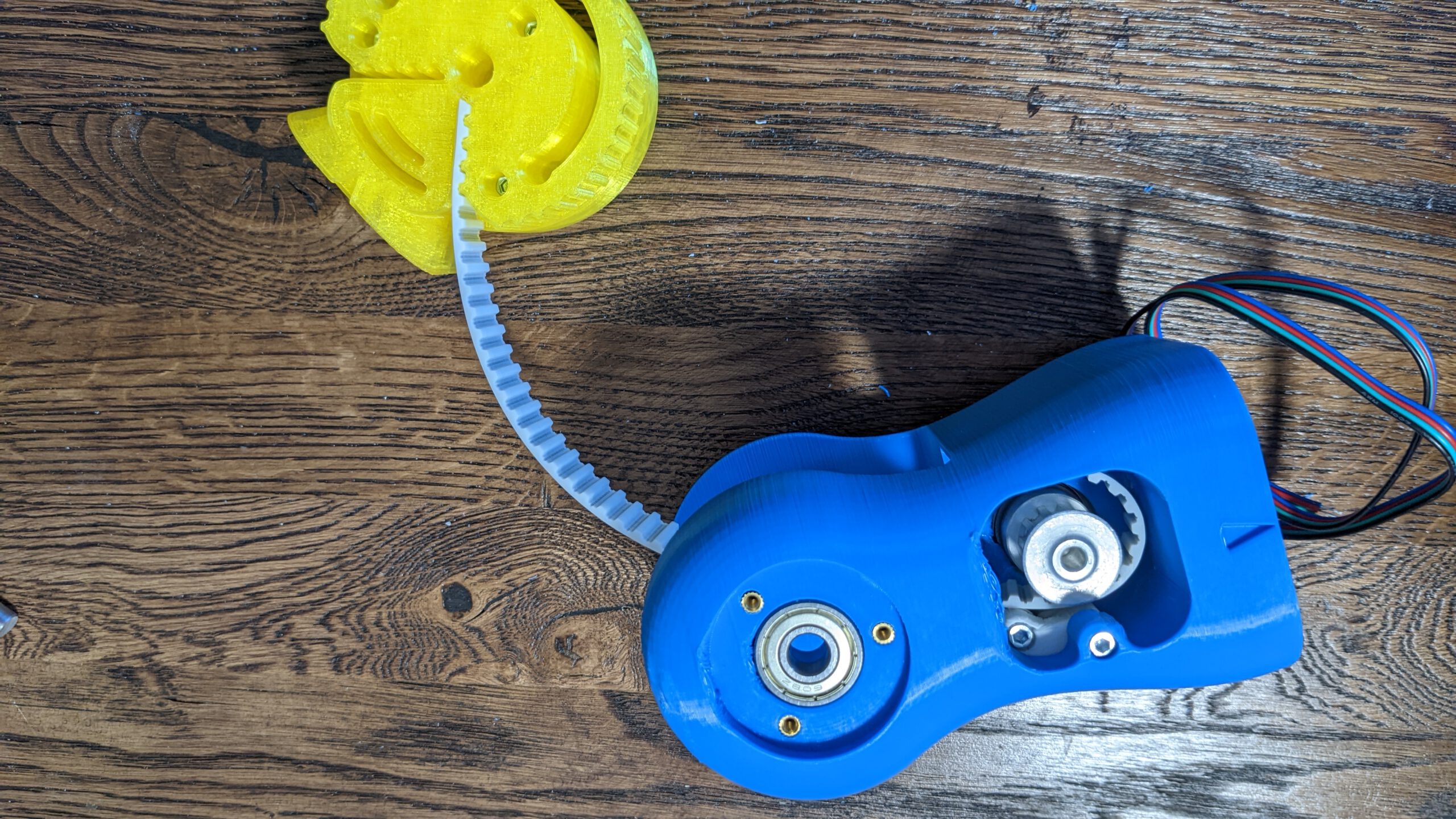
Step 4: Belt stretcher
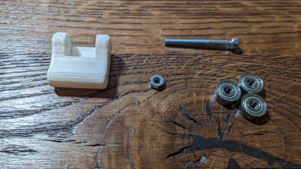
Again my part did not come out perfect. The 3rd bearing did not fit at the first attempt

I filed the left side down so all three bearings have enough place now.
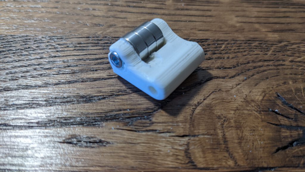
Mounting the belt stretcher was no issue, but I tithed the screw too tight, and the frame broke.
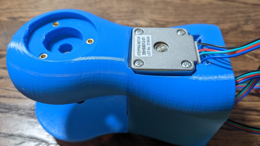
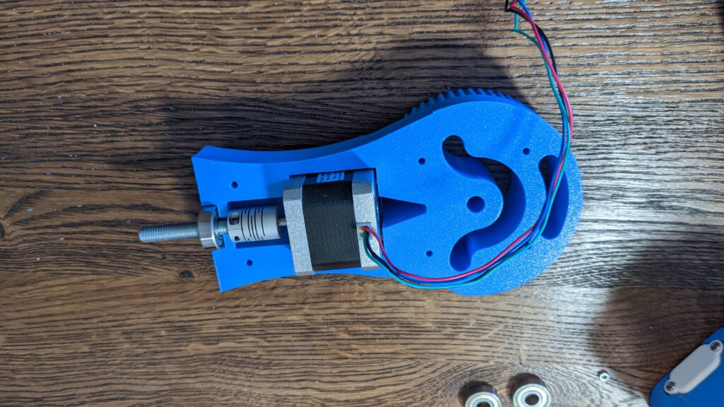
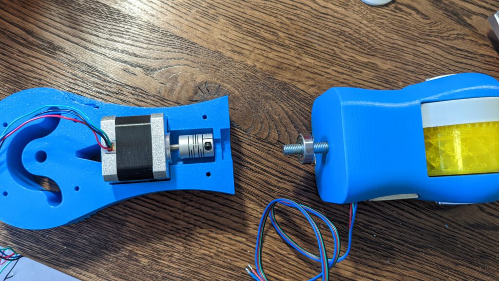
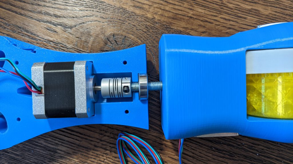
Step 5: Motor mount
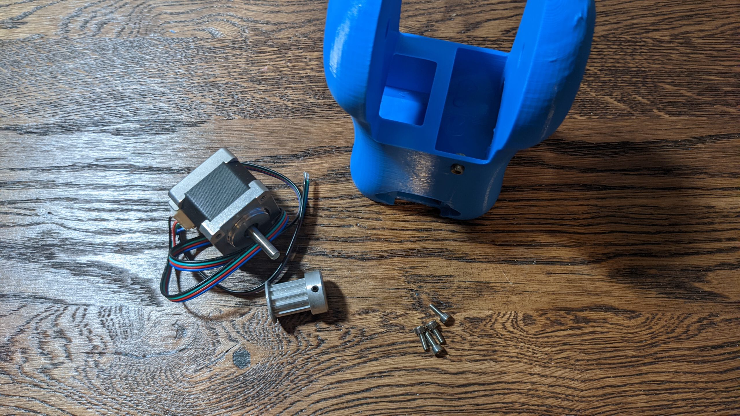
Unfortunately, the motor I purchased did have a plug instead, only wires. The 4M1 is not designed for a motor with a plug on the side.
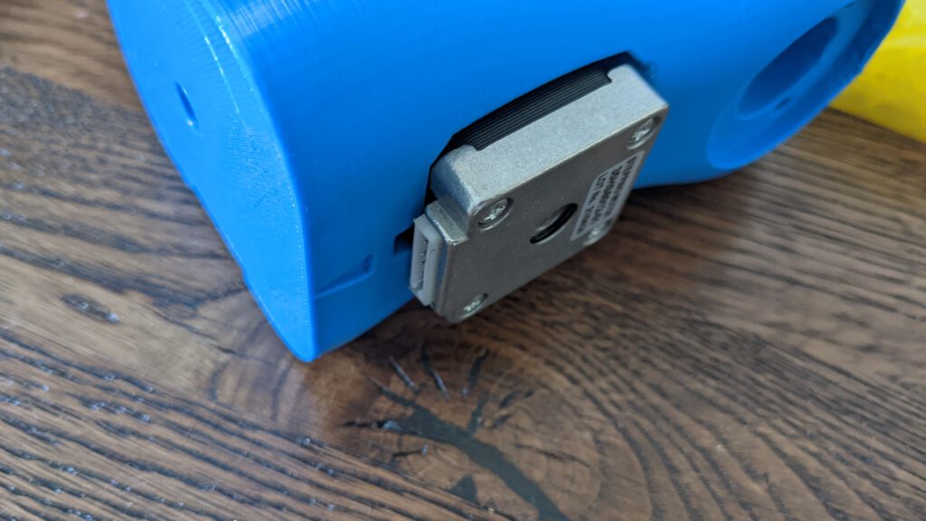
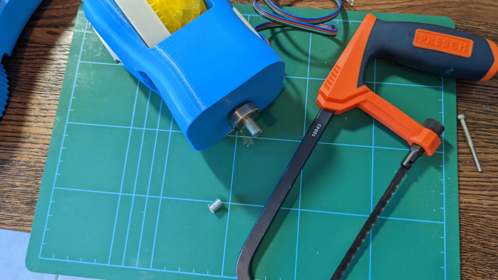
To finish the tutorial in time, I decided to saw out material to fit the motor into the part.
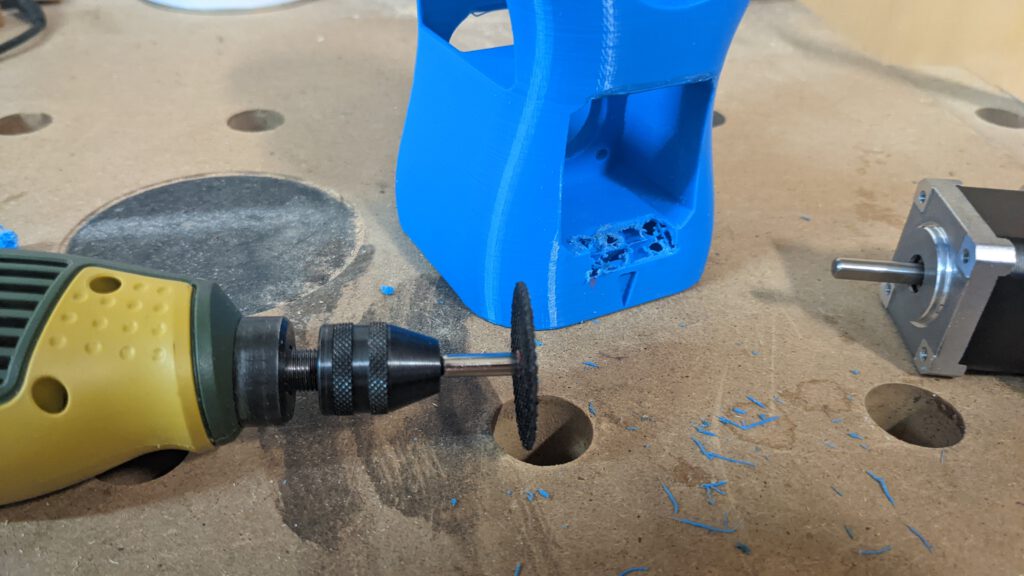
After the cut, the motor fits perfectly. If you have the time to print the 4M1 part again, I will upload a file that contains the out cut, so you don’t have to saw something out by our build.
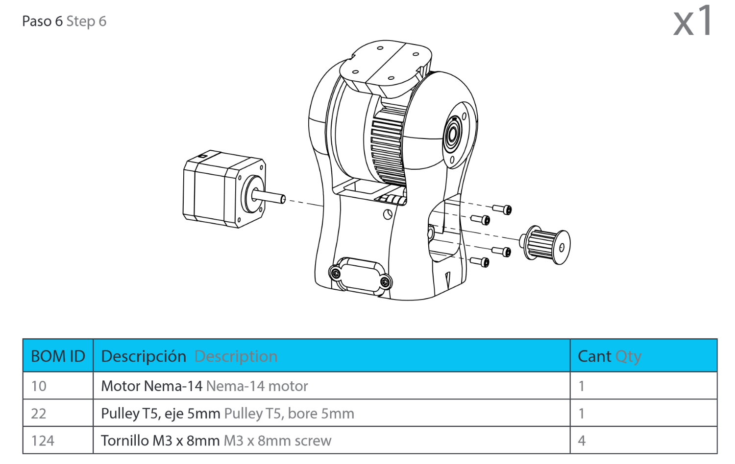
Step 6: The belt
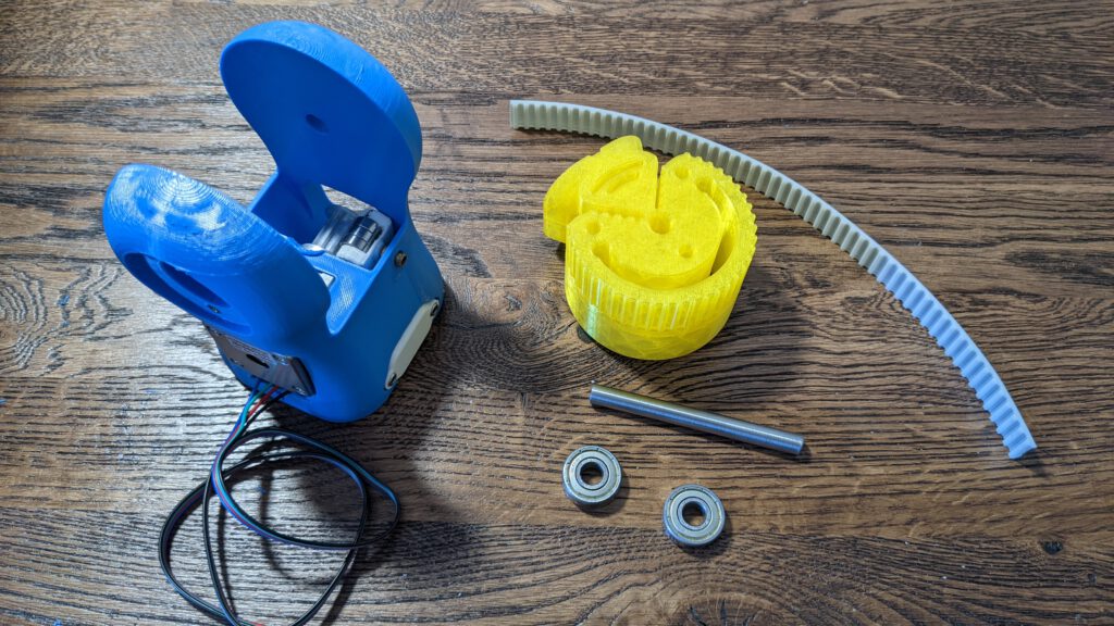
The belt for this part has to be 27.00 cm long. We begin as we begin before. We insert the first end from the belt into the 4M2 assembly
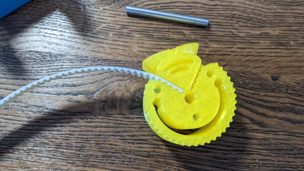
Then we thread through the belt to the hole and around the pulley.
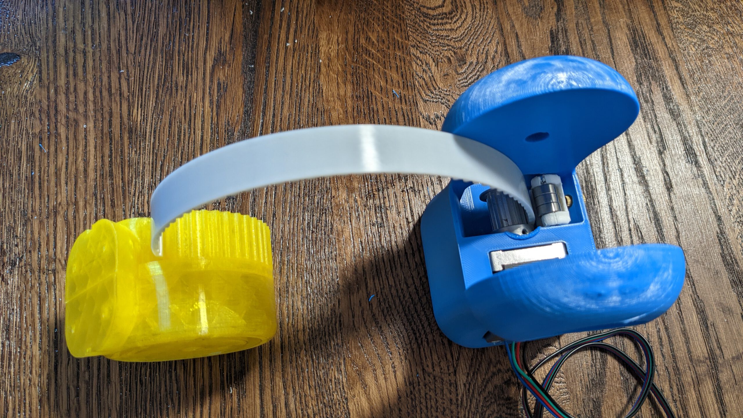
Pull the belt out as far as possible
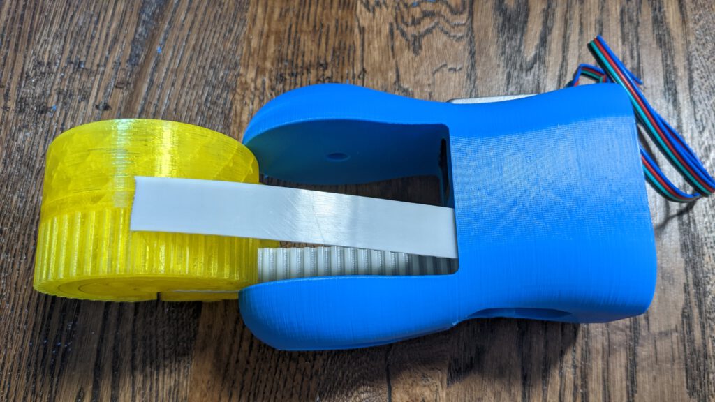
Warp it around the assembly and insert the second end in to its place.

Insert the rod and you have finished this step.
Step 7: Mounting on Module 3
We must disassembly module 3 so we can extract the threaded rod.
Afer this we can screw the rod into module 4.
In my case, however, there was a gab around about 1.1cm long
I cut 1 cm of from the threaded rod.
And now it fits!

Reassembly module 3 with the belt. You can have a look into this chapter if you are not certain how to do it: Part 9.1 Step 5: The Belt
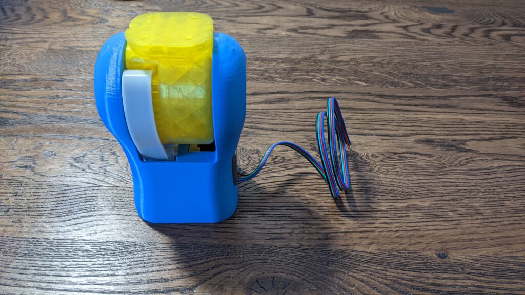
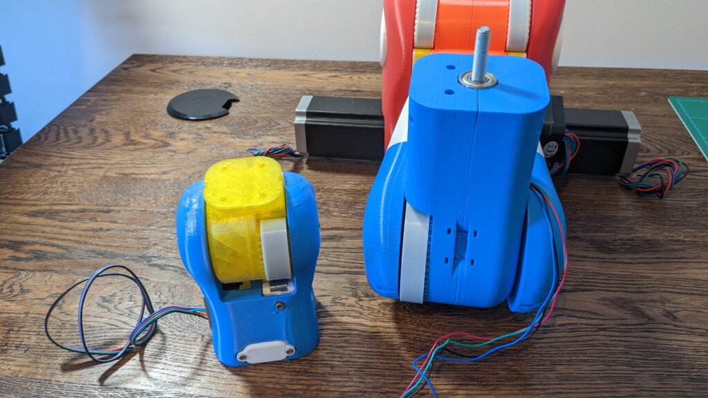
Result Part 10

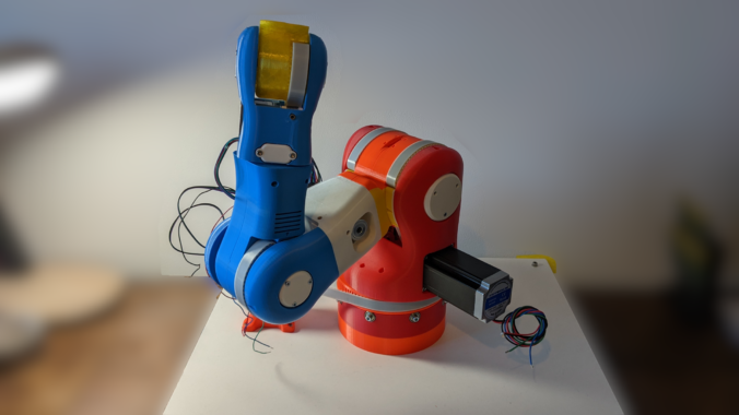
Love it! Keep going 🙂
For this page, step #2, the 4M1 part is assembled with a nut and bearing. My understanding is the 4M1 part is fixed to the shaft/threaded rod and turns with it.
What is the purpose of the bearing inside 4M1 part?